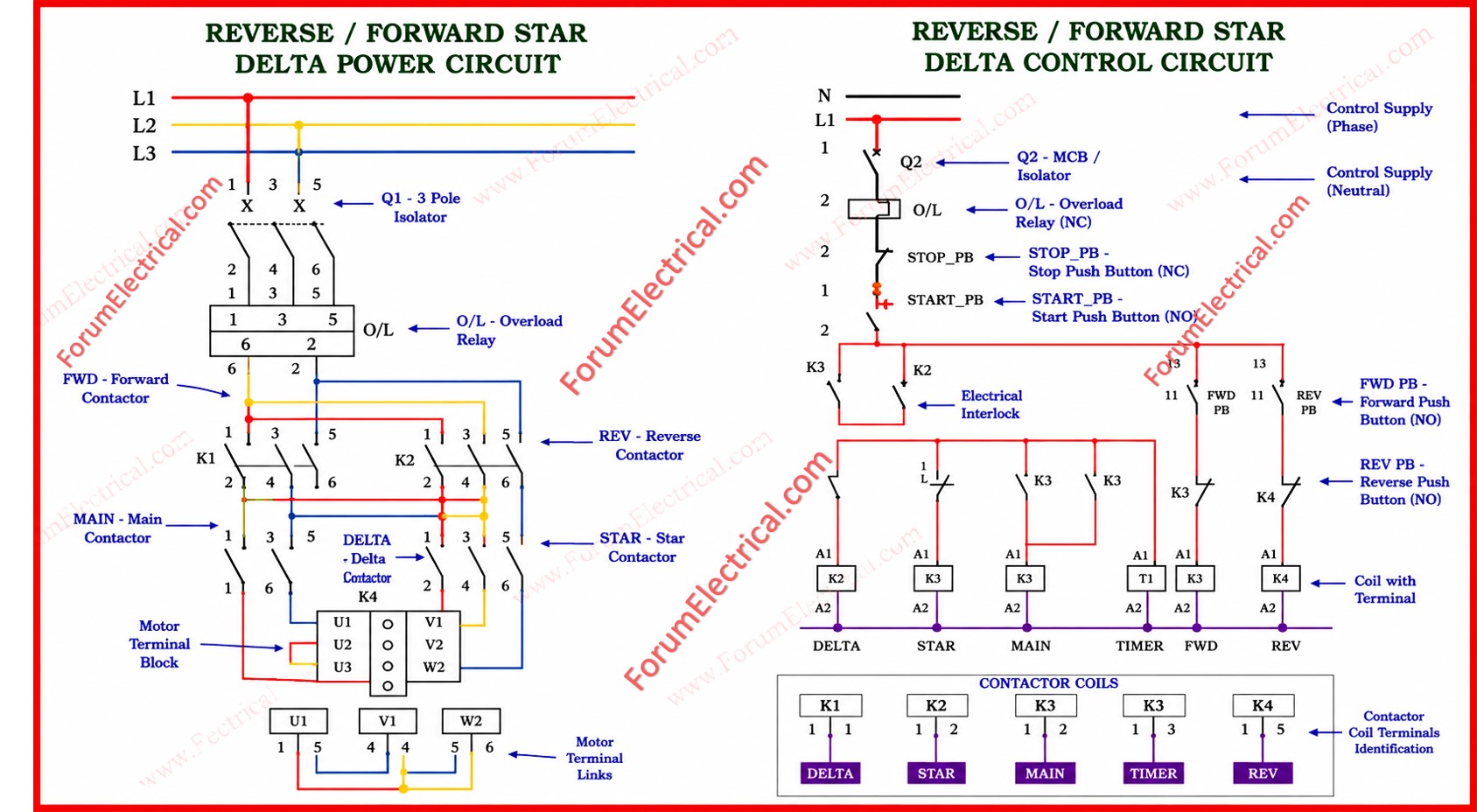
The Forward/Reverse Star-Delta Motor Starter is one of the most commonly used control configurations in heavy duty industrial automation.
It is specifically designed for three-phase induction motors where two primary challenges should be solved simultaneously
- Reducing the high inrush current during startup and
- Enabling bidirectional rotation for process flexibility.
This starter combines direction control (forward and reverse) with a reduced voltage starting method (Star-Delta) to protect both the motor & the supply network.
It is indispensable in
- Conveyor systems,
- Crane hoists,
- Pumping stations,
- Compressors and
- Machine tools.
Components
| Component | Type | Function |
|---|---|---|
| Q1 | MCCB / Circuit Breaker | Short-circuit and overload protection for the whole starter |
| O/L Relay | Thermal / Electronic | Trips if motor runs overcurrent for extended time |
| K1 | Power Contactor | Forward direction – standard phase sequence |
| K2 | Power Contactor | Reverse direction – two phases swapped |
| K3 | Power Contactor | Star (wye) connection – reduced voltage start |
| K4 | Power Contactor | Delta connection – full voltage running |
| T1 | Timer Relay (ON-delay) | Automates Star to Delta transition after preset delay |
| STOP PB | NC Push Button | Removes control supply, stops motor |
| FWD PB | NO Push Button | Initiates forward start sequence |
| REV PB | NO Push Button | Initiates reverse start sequence |
Key Technical Parameters
| Parameter | Value / Description |
|---|---|
| Starting voltage (Star) | VL / √(3) ≈ 58% of line voltage |
| Starting current (Star) | Approx. 1/3 of direct-on-line (DOL) starting current |
| Starting torque (Star) | Approx. 1/3 of DOL starting torque |
| Typical timer delay (T1) | 5 to 15 seconds (load dependent) |
| Control voltage | 24 V DC (or) 110/230 V AC (application specific) |
| Phase reversal method | Swap L1 & L3 at reverse contactor K2 |
| Interlock type | Electrical (NC contacts) + optional mechanical |
| Standard applied | IEC 60947-4-1 (Low-voltage switchgear) |
Power Circuit
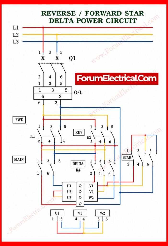
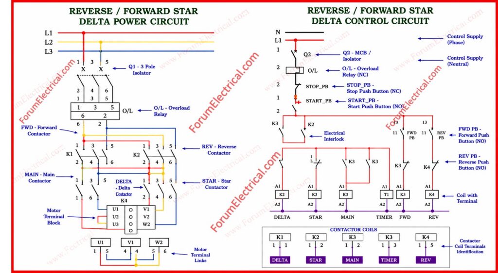
The power circuit carries the high voltage (HV) three-phase (3 Phase) supply directly to the motor windings.
Its components are carefully selected and arranged for safety, protection and performance.
Line Inputs and Protection
Three-phase supply enters via terminals L1, L2 and L3.
2 protective devices are placed in series:
- Q1 (Main Circuit Breaker): Provides short circuit & overload protection for the entire starter. It disconnects the supply instantly under fault conditions.
- O/L (Overload Relay): A thermal (or) electronic relay that monitors running current. If the current exceeds the motor rated value for a sustained period it is used to trip the control circuit and prevent thermal damage to the windings.
Direction Contactors
Two primary contactors handle direction control:
- K1 (Forward Contactor): Connects the motor to L1, L2, L3 in the standard phase sequence that generates clockwise rotation.
- K2 (Reverse Contactor): Swaps two phases (typically L1 and L3), reversing the rotating magnetic field & causing counter-clockwise (anti-clockwise) rotation.
Mechanical and electrical interlocks between K1 & K2 prevent simultaneous energization which would cause a three-phase short circuit.
Star-Delta Contactors
- K3 (Star/Wye Contactor): Connects the ends of the three motor windings to a common neutral point. Each winding receives approximately 58% of line voltage (VL/√3) which is reducing starting current to roughly one-third (1/3)rd of full voltage value.
- K4 (Delta Contactor): After the motor accelerates, K3 opens & K4 closes connecting the windings in a closed delta loop. Each winding now receives full line voltage for rated torque & power output.
Control Circuit
The control circuit operates at a reduced safe voltage (typically 24 V DC (or) 110/230 V AC) and operates the sequence of contactor operations.
Push Buttons
- STOP PB (Normally Closed): De-energises the entire control circuit. Pressing STOP drops out all contactors & the timer.
- FWD PB (Normally Open): Initiates the forward start sequence.
- REV PB (Normally Open): Initiates the reverse start sequence.
Electrical Interlocking
Normally closed (NC) auxiliary contacts from each contactor are placed in series with the coil of the opposing contactor. This electrical interlock ensures:
- K1 cannot energize while K2 is active.
- K2 cannot energize while K1 is active.
- K4 cannot energize while K3 is active.
- K3 cannot energize while K4 is active.
This is an important safety feature. In addition mechanical interlocks (where contactors are physically linked) are often added for redundancy in high risk installations.
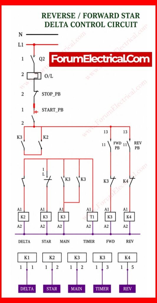
Timer T1 (Star-Delta Transition)
T1 is a time delay relay that automates the Star-to-Delta changeover.
When FWD (or) REV is pressed:
- K1 or K2 energizes (direction selected).
- K3 energizes simultaneously connecting the motor in Star.
- T1 starts counting its preset delay (typically 5 to 15 seconds depending on its motor size & load inertia).
- When T1 times out it opens K3 & closes K4 transitioning the motor to Delta for the full power operation.
Operating Sequence
Forward Start:
- Press FWD PB. K1 and K3 energize. The motor starts in Star (low current, reduced torque).
- T1 starts timing. The motor accelerates under reduced voltage.
- T1 contacts change state. K3 de-energises (Star opens) and K4 energises (Delta closes).
- The motor runs at full voltage and rated torque in Delta.
Reverse Start:
- Press STOP PB first to de-energise K1/K4. Then press REV PB.
- K2 and K3 energise. The motor starts in Star with a reversed phase sequence.
- T1 times out. Transition to Delta as above. The motor runs in reverse at full power.
Typical Industrial Applications
- Conveyor belts & material handling systems requiring bidirectional transport.
- Bridge cranes & overhead hoists (travel in both horizontal directions).
- Lathe, milling & grinding machines needing spindle direction reversal.
- Centrifugal pumps and compressors with a high starting inertia.
- Ventilation fans in tunnels and mines where the airflow direction should be reversible.
- Mixers & agitators in food, chemical and pharmaceutical processing.
Faults, Troubleshooting & Maintenance
A well-designed Forward/Reverse Star-Delta starter is reliable but field engineers must understand common failure modes to minimize downtime.
The most frequent fault is the premature (or) failed Star-to-Delta transition caused by an incorrectly set timer T1.
If the delay is too short the motor has not reached sufficient speed and the Delta contactor closes while the winding current is still high generating a secondary current surge that can exceed the full DOL value.
If the delay is too long then the motor runs in Star indefinitely and starves it of torque & causes overheating.
Troubleshooting Quick Reference
| Symptom | Cause | Corrective Action |
|---|---|---|
| Motor fails to start | STOP PB faulty (open circuit) or O/L relay tripped | Check NC contact of STOP PB; reset O/L relay after inspection |
| Motor starts but won’t reverse | K2 interlock NC contact stuck open | Inspect auxiliary contact block on K1; replace if worn |
| Motor stays in Star | T1 timer not timing out (or) K4 coil open circuit | Check T1 setting; verify K4 coil voltage & continuity |
| Excessive noise at transition | Open-transition causing voltage spike | Upgrade to closed-transition Star-Delta kit |
| O/L relay trips repeatedly | Timer set too short (or) motor overloaded | Increase T1 delay and check mechanical load on shaft |
Standards & Compliance
All forward/reverse star-delta starters utilized in industrial environments should comply with applicable international and national standards.
The primary governing standard is IEC 60947-4-1 which covers low-voltage (LV) AC motor starters including contactors and overload relays.
Panel builders should also observe IEC 61439 for the low voltage switchboard assembly & IEC 60204-1 for electrical safety of machinery.
In regions following NEC (National Electrical Code) guidelines – Article 430 specifies motor branch circuit and overload protection requirements.
CE marking is mandatory for the equipment supplied within the European Economic Area requiring conformity assessment against the Low Voltage (LV) Directive (LVD 2014/35/EU) & the Machinery Directive where applicable.
- Always fit a padlockable isolation switch upstream of Q1 for safe maintenance access.
- Label all terminals clearly with wire ferrules & permanent markers per IEC 60445.
- Perform insulation resistance (IR) tests (500 V DC Megger) before commissioning.
- Document and retain the wiring diagram, timer settings and O/L relay settings inside the panel door for a future maintenance reference.

