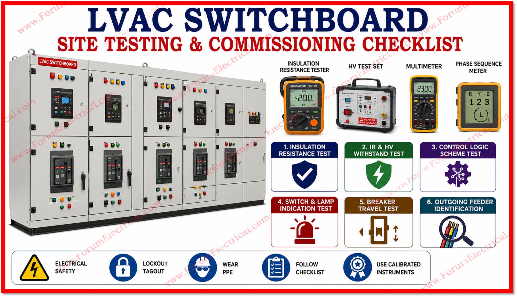
Low Voltage AC (LVAC) switchboard commissioning is a essential activity performed after installation and before energization to ensure that the switchboard is safe, reliable and operates according to the approved design.
- Purpose
- Scope
- Prerequisites before Testing
- Test-1: LVAC Insulation Resistance (IR) Test
- Test-2: LVAC Insulation Resistance & High Voltage (HV) Test
- Test-3: LVAC Scheme (Control Logic) Test
- Test-4: LVAC Switch / Lamp Indication Test
- Test-5: LVAC Breaker Test
- Test-6: LVAC Outgoing Feeder Identification
- Commissioning Sign Off Summary
- Important Notes
- Checklist
- Applicable Standards
The commissioning used to verifies the integrity of
- Busbars,
- Circuit breakers,
- Insulation systems,
- Control wiring,
- PLC logic,
- protection schemes and
- Outgoing feeders.
All work must be carried out under an approved permit to work with lockout/tagout (LOTO) implemented and appropriate personal protective equipment (PPE) worn.
All test instruments shall have valid calibration certificates.
Purpose
This is used to defines the complete site commissioning checklist for a Low Voltage AC (LVAC) switchboard that is covering
- Insulation resistance verification,
- High voltage withstand testing,
- Control scheme functional checks,
- Indication verification,
- Breaker mechanical travel testing and
- Outgoing feeder identification.
The purpose of this checklist is to ensure that the LVAC panel is electrically safe and functionally correct in accordance with the approved design and drawings before the panel is energized & handed over for operation.
Scope
This checklist is intended for use by commissioning engineers, electrical testing personnel and quality assurance/quality control (QA/QC) representatives during the pre energization and site acceptance testing phase of an LVAC switchboard installation that is typically found in power plants, substations and industrial electrical distribution systems.
Prerequisites before Testing
Before commencing any of the tests listed in this checklist the following prerequisites must be confirmed and recorded:
- LVAC panel erection is completed in all respects including mechanical fixing, alignment and earthing connections.
- Bus bar bolted joints and connections have been tightened & verified by torque checks as per the manufacturers torque values.
- All cabling (power and control) has been terminated and inspected for correct routing, ferruling and lug compression.
- Panel internal cleaning has been carried out to avoid construction debris, dust and moisture.
- All protection relay settings & PLC logic have been configured & are made ready for functional verification.
- Calibrated test instruments (1000V IR tester, HV test set, multimeter, phase sequence meter) are accessible with a valid (official) calibration certificates.
- Permit to work and isolation/lock-out-tag-out (LOTO) procedures are in place for personnel safety.
Test-1: LVAC Insulation Resistance (IR) Test
| Objective | To verify the insulation resistance of LVAC bus bars and breakers. |
| Prerequisite | LVAC panel erection completed in all respects; bus bar tightness verified by torque checks. |
| Procedure | With all Air Circuit Breakers (ACBs) in the service position and closed, the insulation resistance is measured between phase-to-phase, phase-to-neutral, phase-to-earth and neutral-to-earth using a 1000V IR tester. |
| Acceptance Criteria | All IR values shall be greater than 200 Mega-ohms. |
Test-2: LVAC Insulation Resistance & High Voltage (HV) Test
| Objective | To verify the insulation resistance of LVAC bus bars and breakers under high voltage stress. |
| Procedure | With all ACBs in the service position and closed, 2kV AC is applied for 1 minute to each phase and neutral, with the other phases and neutral shorted and earthed. Leakage current is recorded during the test. IR is measured both before and after the HV test. |
| Special Precaution | All outgoing feeders shall remain closed during the HV test. Proper maintenance should be taken to ensure that fuses are rated (capability) to withstand the applied 2kV test voltage without damage. |
| Acceptance Criteria | The bus bar shall able to withstand the applied high voltage (HV) for the full duration of 1 minute without breakdown (or) excessive leakage current. |
Test-3: LVAC Scheme (Control Logic) Test
| Objective | To verify the operation logic of the LVAC panel in Auto and Manual mode, as implemented through the PLC program. |
| System Description | The LVAC panel is fed from three incomers sourced from earthing transformers, along with two bus couplers, giving a total of five breakers. Of these five, only three breakers are permitted to be closed simultaneously, and paralleling of the transformers must never be allowed to occur. |
| Key Scheme Checks | With all incomers and bus sections in the service position: all incomers can be closed without paralleling; on failure of any incomer supply, that incomer breaker trips and the corresponding bus section closes automatically to maintain supply to outgoing feeders; on restoration of the failed incomer, the bus section opens first, followed after a time delay by closing of the incomer breaker; and the standby incomer cannot be switched on while any incomer is already in service, and vice versa. |
| Acceptance Criteria | All operations shall conform exactly to the approved control scheme logic. |
| Test Format | Recorded on the scheme test format attached as an annexure to this checklist. |
Test-4: LVAC Switch / Lamp Indication Test
| Objective | To verify the various panel indications and their correct colour coding. |
| Procedure | Indication lamps and semaphore indicators provided on the panel to display device and alarm status are verified for correct function by simulating each respective condition. For example, the breaker test condition is simulated by racking the circuit breaker into the test position. Each possible condition is simulated and checked in turn. |
| Acceptance Criteria | All indications shall match the status and colour defined in the approved test report. |
Test-5: LVAC Breaker Test
| Objective | To verify breaker travel between service, test, and isolated positions without causing tripping of other breakers already in service. |
| Procedure | The test is performed for all required breaker position combinations. The PLC operating mode (PLC function mode) is set to manual for the duration of the test and each circuit breaker (CB) is moved between positions as specified in the test format while that are observing the effect on breakers already in service. |
| Acceptance Criteria | Breakers remaining in the service position shall not trip when other breakers are moved between positions. |
Test-6: LVAC Outgoing Feeder Identification
| Objective | To verify outgoing feeder distribution against the approved drawing and confirm correct cable termination at both the load and source ends. |
| Reference Document | Approved electrical drawing. |
| Procedure | All outgoing feeders are switched off before testing begins. The IR value of the cable is measured for each outgoing feeder. Feeders are then switched on one at a time, with voltage and phase sequence measured at the load end. Terminal tightness, ferrules and insulation resistances are checked and cable sizing and voltage drop at the load end are verified against the design document. |
| Acceptance Criteria | All outgoing feeders shall be terminated in accordance with the drawing, and voltage drop at the load end shall be within allowable design limits. |
Commissioning Sign Off Summary
The following summary table shall be completed & signed by the responsible commissioning engineer upon satisfactory completion of each test.
| S.No | Test Description | Result | Tested By | Date |
|---|---|---|---|---|
| 1 | LVAC Insulation Resistance (IR) Test | Pass / Fail | ||
| 2 | LVAC Insulation Resistance & HV Test | Pass / Fail | ||
| 3 | LVAC Scheme (Control Logic) Test | Pass / Fail | ||
| 4 | LVAC Switch / Lamp Indication Test | Pass / Fail | ||
| 5 | LVAC Breaker Travel Test | Pass / Fail | ||
| 6 | LVAC Outgoing Feeder Identification | Pass / Fail |
Important Notes
- All test instruments used must have a valid calibration certificate traceable to a recognized standard.
- Any deviation from the acceptance criteria shall be recorded as a non conformance and rectified prior to energization.
- Test results must be recorded on the respective test formats & attached as annexures to this checklist.
- Personal protective equipment (PPE) and safe work permits must be used throughout the testing process.
- Final sign off shall be obtained from the consultant representative before the panel is released for energization.
Checklist
Applicable Standards
Overall LVAC panel / assembly
- IEC 61439-1 & IEC 61439-2
- IS/IEC 61439-1 & -2 (Indian adoption)
Test 1 & 2: IR & HV Withstand
- IEC 61439-1, Clause 10.9 (Dielectric properties)
- IEC 61439-1, Clause 10.9.2 (Power-frequency withstand)
- IEC 61557-2 (Insulation resistance test equipment)
- IS 10118 (Part 1–4)
Test 3: Control/PLC Scheme
- IEC 61439-1, Clause 10.13
- IEC 60947-2
Test 4: Indication/Lamp Test
- IEC 60073
- IEC 60204-1
Test 5: Breaker Travel
- IEC 60947-2
- IEC 61439-1, Clause 10.13
Test 6: Outgoing Feeder/Cable
- IEC 60364 / IS 732
- IEC 60228
- IS 1255 / IEC 60502
General
- IEC 60529 (IP rating)
- IS 3043 (Earthing)
- IEEE 1584 (Arc flash safety)

