Circuit breakers are one of the most important components of an electrical power system.
They are switching devices designed to protect equipment and personnel by interrupting fault currents and isolating faulty sections of a network while also allowing the routine switching operations under normal load conditions.
A proper designed breaker should combine fast fault clearance, high mechanical and electrical endurance and reliable operation across a wide range of system conditions.
Understanding how breaker characteristics change across voltage levels is important for engineers involved in the field of design, procurement, operation and maintenance of power systems as the technology, insulation requirements and fault troubleshooting capability all scale with system voltage.
This post is used to presents a consolidated technical overview of circuit breakers used at four common transmission and distribution voltage levels: 33 kV, 132 kV, 220 kV and 400 kV that is covering system parameters, quenching and operating mediums, insulation standards, current ratings, fault handling capability and standard operating sequences.
System Voltage and Frequency
The 4 voltage classes considered here are 33 kV, 132 kV, 220 kV and 400 kV that represents the typical distribution and transmission levels found in most power networks.
The corresponding rated system voltages are 36 kV, 145 kV, 245 kV and 420 kV respectively that is reflecting the maximum voltage the equipment should safely withstand rather than the nominal operating voltage.
Across all four levels the system frequency remains standardized at 50 Hz that is the norm in most countries outside North America and parts of the Americas.
Quenching Medium
The quenching medium is the substance that is used inside the breaker to extinguish the arc that forms when the contacts separate under load (or) fault current.
The choice of medium has a major influence on breaker size, maintenance needs and interruption performance and it evolves noticeably as voltage class increases:
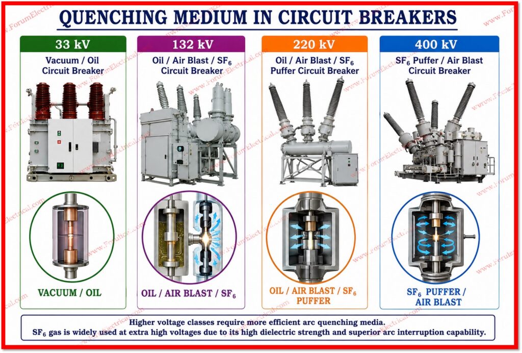
- 33 kV: 33 kV breakers typically use vacuum (or) oil as the interrupting medium as both of which are compact & applicable to distribution level fault currents.
- 132 kV: 132 kV breakers commonly uses oil, air blast (or) SF6 gas providing higher interruption capability for sub transmission networks.
- 220 kV: 220 kV breakers depends on oil, air blast (or) SF6 puffer technology to manage the larger fault energies present at this transmission level.
- 400 kV: 400 kV breakers predominantly utilize SF6 puffer (or) air blast systems since SF6 gives superior dielectric strength and arc quenching performance at extra high voltage.
SF6 (sulphur hexafluoride) gas has become the dominant medium at the higher voltages because of its dielectric strength, effective arc interruption and relatively compact equipment footprint compared to older oil (or) air blast designs.
Operating Mechanism
The operating mechanism supplies the mechanical energy that is required to open and close the breaker contacts rapidly and reliably.
Spring operated mechanisms are used at 33 kV due to their simplicity and low maintenance requirements.
At 132 kV and 220 kV, spring, hydraulic (or) air pressure mechanisms are all used depending on manufacturer and application that is providing higher stored energy for faster operation.
At 400 kV, air pressure mechanisms are typically employed to achieve the very fast and high force operation needed for extra high voltage (EHV) switching duty.
Insulation Standards
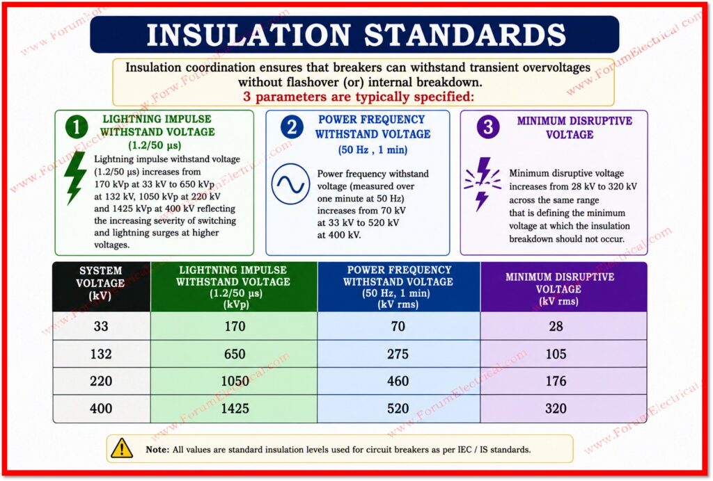
Insulation coordination ensures that breakers can withstand transient overvoltages without flashover (or) internal breakdown.
3 parameters are typically specified:
- Lightning Impulse withstand voltage (1.2/50 μs): Lightning impulse withstand voltage (1.2/50 μs) increases from 170 kVp at 33 kV to 650 kVp at 132 kV, 1050 kVp at 220 kV and 1425 kVp at 400 kV reflecting the increasing severity of switching and lightning surges at higher voltages.
- Power frequency withstand voltage: Power frequency withstand voltage (measured over one minute at 50 Hz) increases from 70 kV at 33 kV to 520 kV at 400 kV.
- Minimum disruptive voltage: Minimum disruptive voltage increases from 28 kV to 320 kV across the same range that is defining the minimum voltage at which the insulation breakdown should not occur.
Current Ratings
Normal current ratings that define the continuous load current a breaker can safely carry.
These range from 1250 A at 33 kV through 1250/1600 A at 132 kV and 2000 A at 220 kV, up to 2000/3150 A at 400 kV reflecting the higher power transfer capacity of extra high voltage (EHV) circuits. Short time current withstand capacity that describes the ability of the breaker to carry fault current for a brief period (typically 3 seconds) without damage is 25 kA at 33 kV and 40 kA at the 132 kV, 220 kV and 400 kV levels.
Fault Handling Capability
Fault ratings that explains how a circuit breaker performs during the making and breaking of short circuit currents that is the most demanding duty it should perform:
- Making capacity: the peak current a breaker can safely close onto during a fault increases from 70 kA at 33 kV to 100 kA at 132 kV, 220 kV and 400 kV.
- Breaking capacity: the symmetrical fault current a breaker can safely interrupt is 25 kA at 33 kV & 40 kA at the higher voltage levels.
- Breaking current out of phase: Breaking current out of phase accounts for the additional stress of interrupting current between phases & ranges from 6.5 kA at 33 kV to 10 kA at 132 kV and above.
- Rated time charging current: the current drawn by the breakers own charging system ranges from 50 A at 33 kV and 132 kV, to 125 A at 220 kV and 400 A at 400 kV.
- Overvoltage factor for switching: Overvoltage factor defined as the ratio of switching surge magnitude to system voltage is capped at 3.0 across all voltage levels to limit transient overvoltage during switching operations.
Operating Sequences
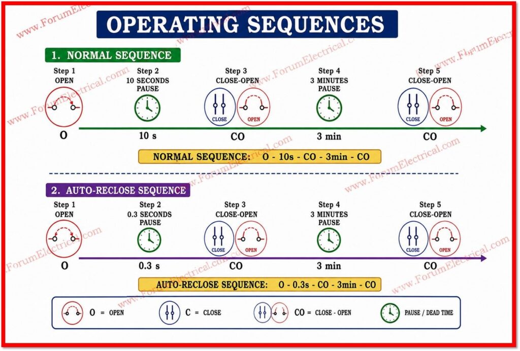
Standard operating procedure (SOP) define how a breaker should perform repeated open-close operations during testing and in service that is simulating both normal switching and the reclosing action which is used after a transient fault:
- Normal sequence: O – 10s – CO – 3min – CO, meaning an opening operation, a 10-second pause, a close-open operation, a 3-minute pause & final close-open operation.
- Auto-reclose sequence: O – 0.3s – CO – 3min – CO, where the much shorter 0.3-second dead time reflects the rapid reclosing need to restore supply after a transient line fault while allowing the arc path to de-ionise.
Consolidated Technical Particulars
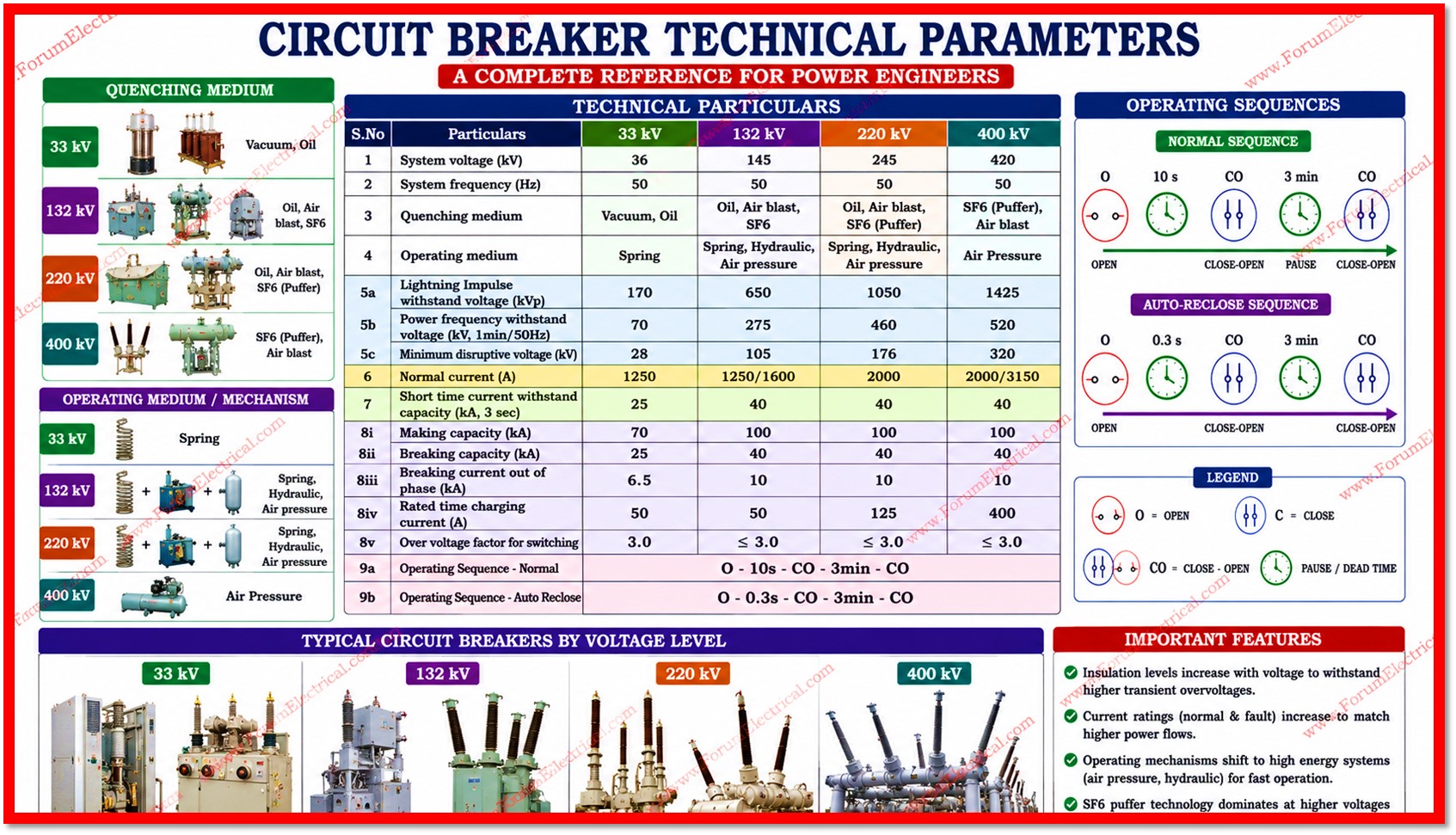
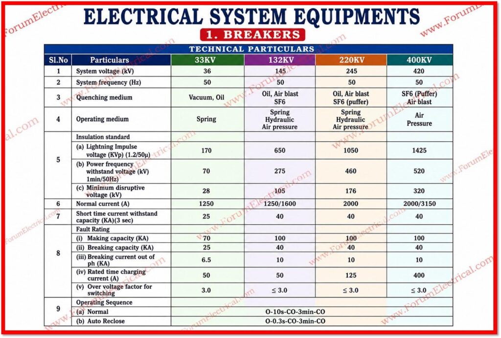
The table below consolidates the important technical particulars of circuit breakers across the 4 voltage classes for quick reference.
| S.No | Particulars | 33 KV | 132 KV | 220 KV | 400 KV |
|---|---|---|---|---|---|
| 1 | System voltage (kV) | 36 | 145 | 245 | 420 |
| 2 | System frequency (Hz) | 50 | 50 | 50 | 50 |
| 3 | Quenching medium | Vacuum, Oil | Oil, Air blast, SF6 | Oil, Air blast, SF6 (Puffer) | SF6 (Puffer), Air blast |
| 4 | Operating medium | Spring | Spring, Hydraulic, Air pressure | Spring, Hydraulic, Air pressure | Air Pressure |
| 5a | Lightning Impulse withstand voltage (kVp) | 170 | 650 | 1050 | 1425 |
| 5b | Power frequency withstand voltage (kV, 1min/50Hz) | 70 | 275 | 460 | 520 |
| 5c | Minimum disruptive voltage (kV) | 28 | 105 | 176 | 320 |
| 6 | Normal current (A) | 1250 | 1250/1600 | 2000 | 2000/3150 |
| 7 | Short time current withstand capacity (kA, 3 sec) | 25 | 40 | 40 | 40 |
| 8i | Making capacity (kA) | 70 | 100 | 100 | 100 |
| 8ii | Breaking capacity (kA) | 25 | 40 | 40 | 40 |
| 8iii | Breaking current out of phase (kA) | 6.5 | 10 | 10 | 10 |
| 8iv | Rated time charging current (A) | 50 | 50 | 125 | 400 |
| 8v | Over voltage factor for switching | 3.0 | ≤ 3.0 | ≤ 3.0 | ≤ 3.0 |
| 9a | Operating Sequence – Normal | O – 10s – CO – 3min – CO | |||
| 9b | Operating Sequence – Auto Reclose | O – 0.3s – CO – 3min – CO | |||
Important Features
As system voltage increases from 33 kV to 400 kV, every major circuit breaker parameter scales upward in a consistent pattern: insulation withstand levels increase sharply to cope with higher transient overvoltages, normal and fault current ratings increase to match larger power flows and operating mechanisms shift toward faster and higher energy systems such as air pressure and hydraulic drives.
SF6 puffer technology increasingly dominates at higher voltages because of its superior arc extinguishing properties, compact design and proven reliability in extra high voltage transmission networks.
Selecting the correct breaker technology and rating for a given voltage class is therefore fundamental to ensuring both the safety and long term reliability of the power system.

