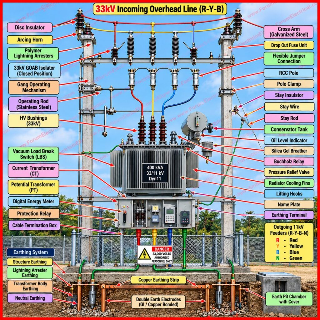
A 33 kV pole-mounted transformer installation is a medium-voltage (MV) step down arrangement mounted on robust utility poles that is commonly configured as H-poles and used to reduce a 33000 V sub transmission supply to a distribution level of 11000 V (or) to local secondary levels.
This configuration is widely adopted for rural feeders, agricultural loads and semi urban distribution networks where installing a dedicated substation building is not economical.
Because the assembly carries high voltage and supports the significant weight of an oil-filled transformer at height, the design integrates protection, isolation and mechanical support elements in a single compact structure.
This post describes the electrical circuit path from the incoming 33 kV supply to the outgoing 11 kV feeder explains the function of each major component and sets out the actionable steps required for a safe & compliant field installation.
Circuit Path and Component Functions
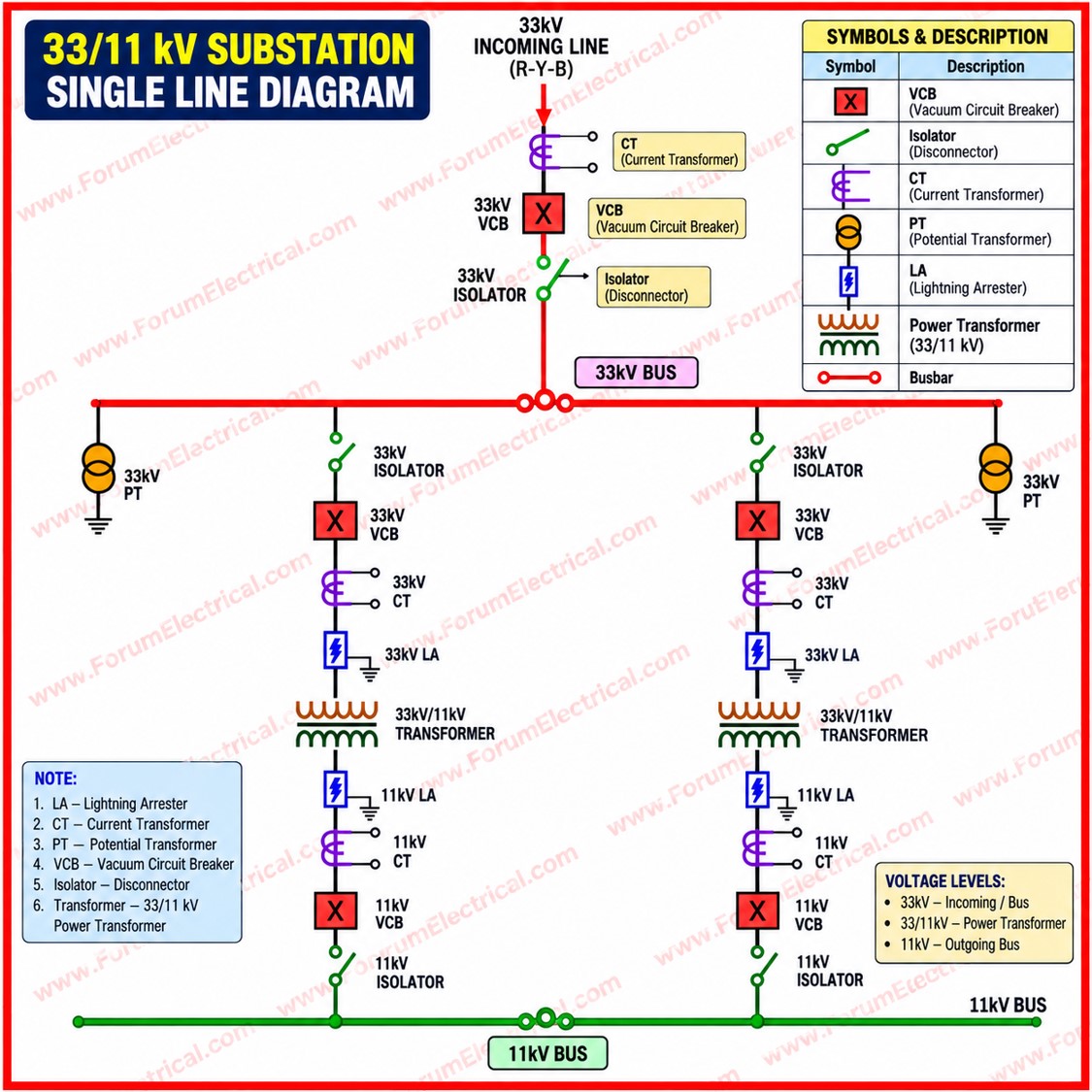
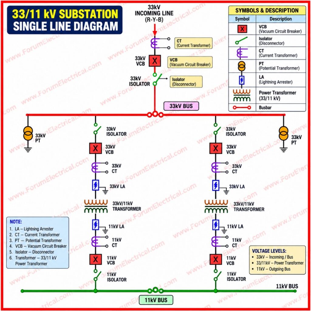
Electrical power flows through the pole-mounted assembly in a defined top to bottom sequence with each stage performing a specific protective, switching (or) transformation role before the supply reaches the outgoing feeder.
| Component | Function |
|---|---|
| 33 kV Incoming Line | Overhead sub-transmission conductors delivering 33000 V from the source substation that is supported on disc (or) pin insulators at the pole top. |
| Lightning Arrester (LA) | First line of defense; diverts lightning and switching surges to earth before they reach the transformer. |
| Isolator / GOAB Switch | Gang Operated Air Break switch allowing manual, visible circuit isolation for safe maintenance. |
| Drop-Out (DO) Fuse | Overcurrent protection and the fuse carrier physically drops open on a fault that is giving a clear visual trip indication. |
| 33/11 kV Transformer Unit | Oil-filled ONAN-cooled core with HT delta primary and LT star (grounded neutral) secondary windings; fitted with the conservator tank and silica gel breather. |
| 11 kV Outgoing Line | Carries the stepped down medium voltage onward to local (or) secondary distribution networks. |
Equipment generally adheres to IEC 60076 (for power transformers) and local equivalents like IS 2026/IS 1180 in South Asia.
Installation Procedure
Structural Preparation
Confirm that the concrete or steel H-poles are erected securely with foundation depth and backfilling suited to local soil conditions.
The structure mechanical load rating should comfortably exceed the combined static and dynamic weight of the oil-filled transformer, cross-arms and line hardware, including allowances for wind loading.
Lifting and Positioning
Use only certified lifting gear and cranes rated safely above the combined weight of the transformer tank, oil and accessories.
Plan vehicle access routes in advance, and maintain adequate rigging clearance from live lines and other structures throughout the lift to avoid inadvertent contact (or) structural overload.
Grounding and Earthing
Install comprehensive copper earthing strips connected to deep earth pits, bonding the transformer tank body, the LT neutral point and the lightning arrester earth terminals.
Low and stable earth resistance is essential to ensure rapid dissipation of fault currents and to hold touch and step potentials within safe limits.
HT/LT Connection
Connect the high-tension jumpers from the drop-out fuse outputs to the 33 kV HT bushings, and terminate the 11 kV secondary cables at the LT bushings.
Phase sequence should be checked and maintained as R-Y-B throughout since incorrect phase orientation can cause downstream equipment malfunction (or) unsafe paralleling conditions.
Post-Installation Inspection
Before energizing the transformer complete the following verification checks:
- Insulation resistance (Megger) testing of HT and LT windings to earth and between windings.
- Dielectric breakdown voltage (BDV) testing of the insulating oil to confirm it meets acceptable withstand levels.
- Physical inspection of all mechanical bolts, structural clearances and terminal connections for tightness and correct torque.
- Verification of earth pit continuity and also measured earth resistance values.
- Confirmation of correct phase sequence and tap changer position prior to charging the line.
Summary
A 33 kV pole-mounted transformer installation combines insulated overhead conductors, surge protection, manual isolation, fuse protection and an oil-filled step down transformer into a single elevated assembly.
Each component performs a distinct function in the sequence from incoming supply to outgoing feeder and safe commissioning depends equally on sound structural preparation, correct grounding, proper HT/LT termination and thorough post-installation testing.
Adherence to these practices ensures reliable, long term operation of the distribution network while protecting personnel and equipment.

