Battery Energy Storage System (BESS)
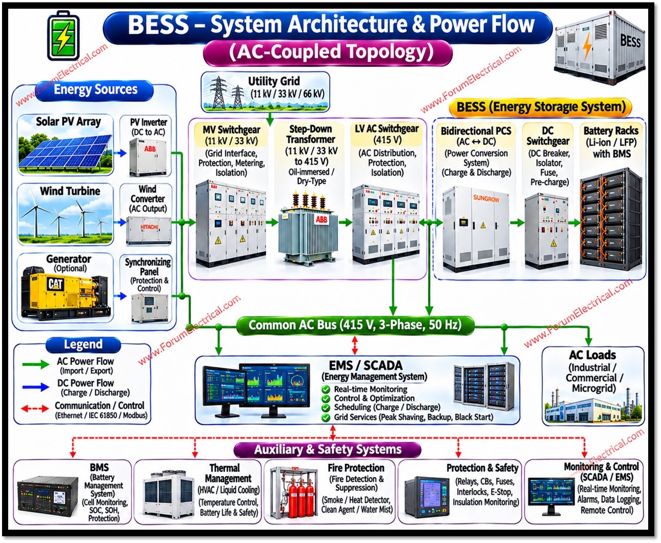
A Battery Energy Storage System (BESS) is an integrated installation that stores electrical energy in electrochemical batteries and releases it as electricity when required.
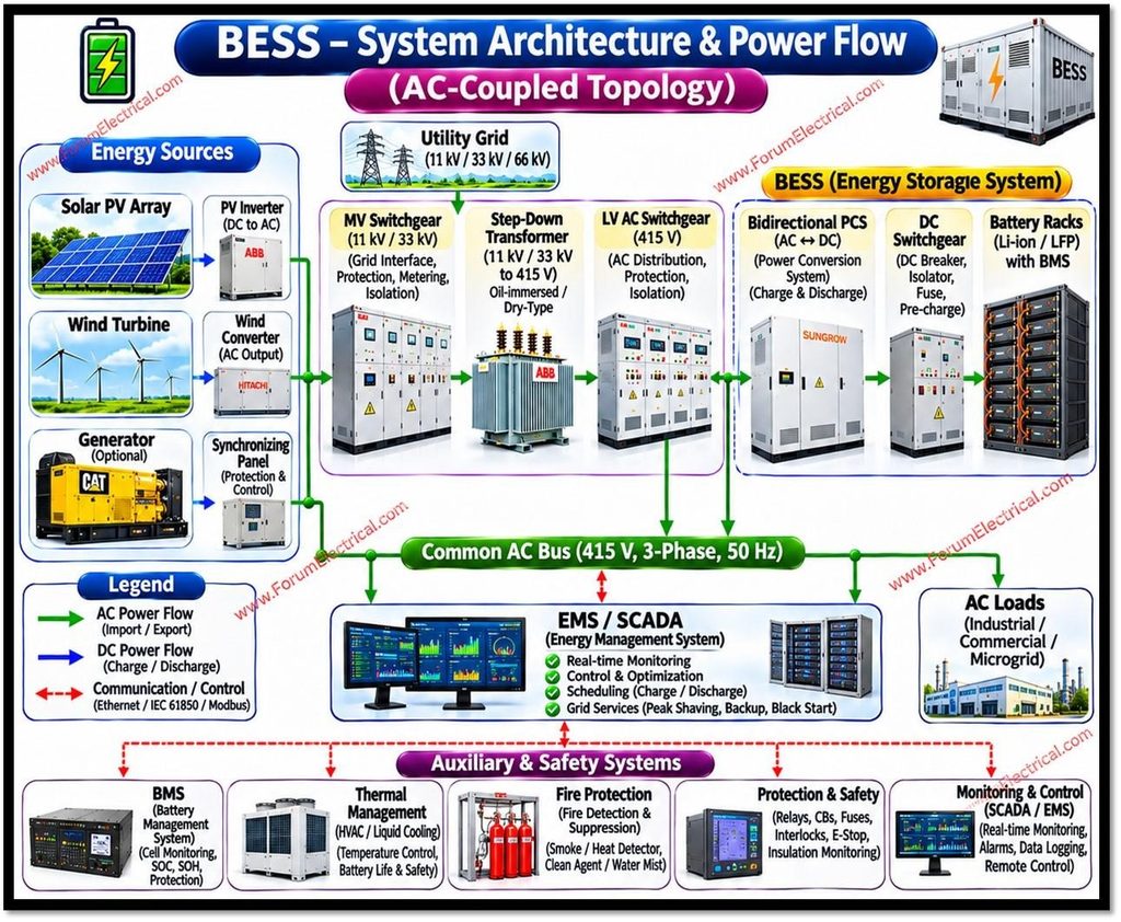
It is not just a battery: a BESS combines the battery cells with power conversion equipment, monitoring and control systems, thermal management, protection and safety systems, so that stored energy can be exchanged safely and controllably with an electrical grid, a renewable generator (or) a local load.
- Battery Energy Storage System (BESS)
- Technical Terms
- Power vs. Energy
- BESS Technical Parameters
- Formula
- System Configurations and Deployment Scales
- Coupling Architectures
- Deployment Scale and Location
- Applications
- Sizing a BESS
- Solved Example
- Performance, Degradation and Lifetime of BESS
- Degradation Mechanisms in Lithium-Ion Cells
- Factors affecting Life
- Safety, Codes and Standards
- BESS Components Cost
- Why Energy Storage is required?
- System Architecture and Components
- Battery Cells, Modules and Racks
- Battery Management System (BMS)
- Power Conversion System (PCS)
- Energy Management System (EMS) and Plant Controller
- Thermal Management System (TMS)
- Electrical Balance of Plant
- Fire Detection and Suppression and Enclosure
- Energy Flow and Loss Points
- Battery Technologies and Chemistries
- Why LFP dominates Grid Storage?
- Flow Batteries
- Other Technologies
A BESS operates in 2 modes:
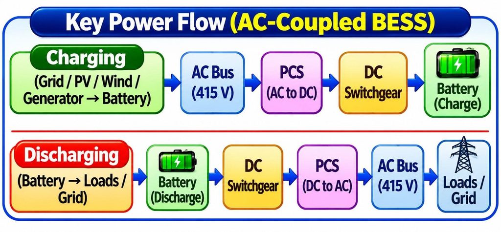
- Charging: Electrical energy from the grid (or) a generator is converted from AC to DC by a bidirectional power converter and stored chemically in the battery.
- Discharging: The stored chemical energy is converted back to DC electricity and then inverted to AC at the required voltage and frequency and delivered to the grid or load.
BESS is a subset of the wider category of Electrical Energy Storage (EES), which also includes pumped hydro storage, compressed-air energy storage, flywheels, thermal storage and hydrogen.
Pumped hydro remains the largest form of grid storage by installed energy capacity worldwide, while batteries have become the fastest-growing segment because of falling costs, modular construction, fast response and flexible siting.
Technical Terms
| Term | Meaning |
|---|---|
| BESS | Battery Energy Storage System. |
| BMS | Battery Management System. |
| PCS | Power Conversion System (bidirectional inverter/converter). |
| EMS | Energy Management System. |
| SCADA | Supervisory Control and Data Acquisition. |
| SoC / SoH / DoD | State of Charge / State of Health / Depth of Discharge. |
| RTE | Round-Trip Efficiency. |
| LFP / NMC / NCA / LTO | Lithium iron phosphate / nickel manganese cobalt / nickel cobalt aluminium / lithium titanate chemistries. |
| LCOS | Levelized Cost of Storage. |
| PPA | Power Purchase Agreement. |
| POI | Point of Interconnection (where the plant connects to the grid). |
| VGF | Viability Gap Funding. |
| LDES | Long-Duration Energy Storage. |
| Augmentation | Adding battery capacity over time to offset degradation. |
| Thermal runaway | Uncontrolled self-heating exothermic reaction in a cell. |
Power vs. Energy
Two ratings define every BESS and are frequently confused:
- Power capacity (kW or MW): The maximum rate at which the system can charge or discharge. It is determined mainly by the power conversion system.
- Energy capacity (kWh or MWh): The total amount of energy the system can store & deliver. It is determined mainly by the amount of battery installed.
The ratio of the two gives the duration. A system rated 100 MW / 400 MWh can discharge at full power for four hours (400 MWh ÷ 100 MW) subject to usable-capacity and efficiency considerations covered later.
Duration (h) = Energy capacity (MWh) ÷ Power capacity (MW)
BESS Technical Parameters
| Parameter | Definition | Notes |
|---|---|---|
| Rated power (kW/MW) | Maximum continuous charge or discharge power at the point of connection. | Set by PCS rating and grid-connection limits. |
| Nameplate energy (kWh/MWh) | Total energy the installed battery can store when new, usually at DC level. | Differs from usable and delivered AC energy. |
| Usable energy | Energy accessible within the allowed SoC window. | Reduced by reserved top and bottom SoC margins. |
| State of Charge (SoC) | Present stored energy as % of current full capacity. | Estimated, not directly measured. |
| State of Health (SoH) | Present capacity (or) resistance relative to new in %. | Commonly 80% capacity is treated as end-of-life in warranties, though definitions vary. |
| Depth of Discharge (DoD) | Fraction of discharged capacity (a cycle). | Deeper cycling generally shortens life for most chemistries. |
| C-rate | Charge or discharge current relative to capacity: 1C discharges the full capacity in 1 hour; 0.5C in 2 hours; 0.25C in 4 hours. | Higher C-rate means more heat and loss. |
| Round-trip efficiency (RTE) | Energy discharged ÷ energy charged over a full cycle, measured at a stated point (DC or AC). | AC-AC RTE includes PCS, transformer and auxiliaries; always specify the measurement boundary. |
| Cycle life | Number of cycles before capacity falls to a defined threshold under stated conditions. | Depends on DoD, C-rate and temperature. |
| Calendar life | Time-based ageing even without cycling. | Accelerated by high temperature and high SoC storage. |
| Response time / ramp rate | Time to move from standby to a power set-point, and MW/min rate. | Battery systems typically respond in milliseconds to hundreds of milliseconds, depending on controls. |
| Availability | Share of time the system can deliver rated service. | Often contractually guaranteed (for example in an O&M agreement). |
| Auxiliary consumption | Energy used by HVAC, controls and other loads. | Counted against AC round-trip efficiency. |
Principal BESS performance parameters.
Formula
Power (kW) = Voltage (V) × Current (A) ÷ 1000 (DC)
Energy (kWh) = Average power (kW) × Time (h)
C-rate = Current (A) ÷ Rated capacity (Ah)
RTE (%) = Energy discharged (kWh) ÷ Energy charged (kWh) × 100
System Configurations and Deployment Scales
Coupling Architectures
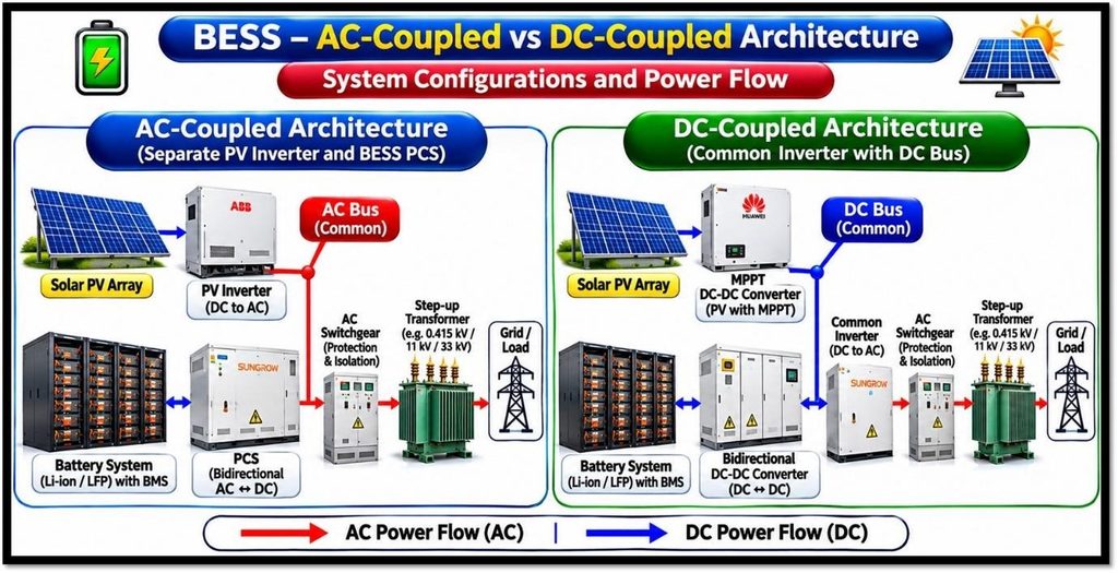
When a BESS is paired with solar PV, two primary electrical arrangements exist:
| Feature | AC-coupled | DC-coupled |
|---|---|---|
| Connection | Battery has its own PCS connected to the AC side; PV has its own inverter. | Battery connects through a DC-DC converter to the DC bus shared with PV, using a common inverter. |
| Retrofit to existing PV | Straightforward | More difficult; usually suited to new builds |
| Conversion steps for PV-to-battery energy | Two (DC→AC→DC) | One (DC→DC), so higher efficiency for that path |
| Flexibility | Battery can charge from the grid or PV independently of PV output | Charging from the grid depends on the shared inverter and design; clipped PV energy can be recovered |
| Typical use | Standalone storage, retrofits, grid-service-focused plants | New solar-plus-storage plants where recovering clipped energy is valuable |
Comparison of AC-coupled and DC-coupled BESS
Deployment Scale and Location
| Category | Typical size | Connection point | Primary purposes |
|---|---|---|---|
| Residential | ≈3–20 kWh | Behind the meter, single or three-phase | Self-consumption of rooftop solar, backup, tariff optimization |
| Commercial and industrial (C&I) | ≈100 kWh to several MWh | Behind the meter, low or medium voltage | Peak-demand charge reduction, backup, power quality |
| Utility-scale / front-of-meter | Tens of MW to several hundred MW; one to several hundred MWh up to multi-GWh | Transmission or distribution network | Market services, capacity, renewable integration, grid support |
| Microgrid / off-grid | kW to tens of MW | Islandable local network | Reliable supply with diesel displacement and renewables |
Categories of BESS by scale and location (indicative sizes)
Applications
A single BESS can often provide several services in sequence or simultaneously, a practice known as value stacking, subject to market rules, technical limits on energy and power, and contractual constraints.
| Application | Description | Technical Requirement |
|---|---|---|
| Energy arbitrage / time shifting | Charge when prices or system cost are low and discharge when high. | Energy capacity (usually 2–4+ hours), high RTE |
| Frequency regulation | Rapidly inject or absorb power to hold system frequency near its nominal value (50 Hz in India and Europe; 60 Hz in North America). | High power, fast response, narrow SoC swings |
| Spinning/fast-reserve substitutes and contingency reserve | Provide reserve power after generator or line loss. | Fast response, reliable availability |
| Synthetic/fast frequency response and inertia | Emulate inertial response via fast power injection or grid-forming control. | Advanced inverter control |
| Capacity / resource adequacy | Provide firm capacity to meet peak demand. | Guaranteed duration at rated power during defined windows |
| Renewable firming and smoothing | Reduce short-term variability of PV or wind output; meet ramp-rate limits. | Fast response, moderate energy |
| Renewable energy shifting / curtailment avoidance | Store surplus renewable energy for later delivery. | Several hours of storage |
| Voltage and reactive power support | Inject or absorb reactive power via the PCS. | PCS apparent power (kVA) margin |
| Transmission and distribution deferral | Offset peak loading on constrained assets to delay reinforcement. | Local siting, sufficient energy for the peak duration |
| Black start | Restart parts of the powergrid after a blackout without any external supply. | Grid-forming capability, adequate energy and surge capacity |
| Peak shaving (or) Demand-charge management | Reduce the consumer maximum demand from the grid. | Matched to load profile and tariff |
| Backup and resilience | Supply critical loads during outages. | Islanding capability, reserved SoC |
| EV charging support | Buffer high-power chargers to limit grid demand. | High power relative to energy |
Major BESS applications
Sizing a BESS
Sizing balances service requirements, economics and technical limits. A typical process is:
- Define the use case(s) and the revenue or benefit for each (for example, a contract for 100 MW for 4 hours daily).
- Determine required power (MW): driven by the maximum discharge and charge power needed at the point of connection, including any reactive power requirement.
- Determine required deliverable energy (MWh at AC): power multiplied by duration, plus any additional energy for multiple services.
- Account for losses and limits: round-trip efficiency, auxiliary load, usable SoC window, and ageing over the project life.
- Decide on augmentation strategy: oversize initially or add battery blocks over time to maintain contracted capacity.
- Check against grid-connection limits, site area and safety separation distances.
Solved Example
Deliver 100 MW for 4 hours (400 MWh) at the point of connection at the end of year 10. Assume 2% capacity loss per year (a simplified compound model), and a usable-to-nameplate ratio of 95% for the SoC window.
This is an illustrative calculation, not a design recommendation.
| Step | Calculation | Result |
|---|---|---|
| 1. Required delivered energy (AC) | 100 MW × 4 h | 400 MWh |
| 2. Capacity retention after 10 years | 0.98¹⁰ | ≈0.817 (81.7%) |
| 3. Usable fraction of nameplate | Given | 0.95 |
| 4. Required nameplate energy at beginning of life (ignoring discharge-side losses already included in the AC requirement) | 400 ÷ (0.817 × 0.95) | ≈515 MWh |
| 5. Charge energy per daily cycle at start, if AC RTE = 85% and 400 MWh is delivered | 400 ÷ 0.85 | ≈470.6 MWh drawn from the grid |
| 6. Energy lost per cycle | 470.6 − 400 | ≈70.6 MWh |
Performance, Degradation and Lifetime of BESS
Degradation Mechanisms in Lithium-Ion Cells
- SEI (solid electrolyte interphase) growth on the anode consumes lithium and electrolyte, causing capacity loss and resistance increase. It accelerates with temperature and is a major calendar-ageing mechanism.
- Lithium plating can occur when charging at high rates or low temperatures, causing irreversible lithium loss and, in severe cases, safety hazards.
- Cathode structural changes and transition-metal dissolution, particularly at high voltage and temperature.
- Mechanical stress from electrode expansion and contraction during cycling, leading to particle cracking and loss of contact.
- Electrolyte decomposition and gas generation.
Factors affecting Life
| Factor | Effect on life | Mitigation |
|---|---|---|
| High temperature | Accelerates calendar and cycle ageing | Effective thermal management; site design |
| Low temperature charging | Raises plating risk | Heating; BMS charge-current limits |
| High SoC dwell | Accelerates side reactions | Operate at moderate SoC when idle |
| High C-rate | More heat and stress | Size energy for lower C-rate (longer duration) |
| Deep cycling | More wear per cycle | Appropriate DoD; oversizing |
| Cell imbalance | Weakest cell limits pack | Balancing; quality matching of cells |
Operating factors that influence battery life
Safety, Codes and Standards
Principal Hazards
The most significant hazard associated with lithium-ion BESS is thermal runaway: a self-accelerating exothermic reaction inside a cell, triggered by overheating, overcharge, internal short circuit, mechanical damage or manufacturing defects. It can release flammable and toxic gases and heat that propagates to neighbouring cells. Key points:
- Self-heating of lithium-ion cells can begin at temperatures in the vicinity of 80–120 °C, and separator melting occurs at higher temperatures (around 130 °C for polyethylene and about 165 °C for polypropylene), allowing internal short circuits.
- Off-gas typically contains hydrogen, carbon monoxide, carbon dioxide, hydrocarbons and electrolyte vapours, creating fire and explosion risk if gas accumulates in an enclosure.
- Other hazards include electric shock and arc flash (high DC voltage and fault current), toxic or corrosive materials, and for flow batteries, electrolyte spills.
Design Safeguards
- Cell-level protection: current interrupt devices, vents, and quality controls in manufacturing.
- BMS monitoring and power limiting, with independent hardware protections.
- Thermal management and early detection (gas, smoke, temperature) with automatic shutdown.
- Physical separation between units, fire-rated barriers, and spacing from buildings per code.
- Explosion prevention or venting according to applicable standards.
- Emergency response planning and training for operators and firefighters.
- Large-scale fire testing to evaluate propagation and the design basis.
Key Standards and Codes
| Standard | Scope (Summary) |
|---|---|
| UL 9540 | Safety of energy storage systems and equipment (system level). |
| UL 9540A | Test method for evaluating thermal runaway fire propagation in battery energy storage systems. |
| UL 1973 | Batteries for use in stationary applications. |
| UL 1642 | Lithium batteries (cell level safety). |
| IEC 62619 | Safety requirements for the secondary lithium cells & batteries for all industrial applications. |
| IEC 63056 | Safety requirements for the secondary lithium cells and batteries (all) for electrical energy storage systems. |
| IEC 62933 series | Electrical energy storage systems: terminology, unit parameters and testing methods, safety, environmental issues and grid integration. |
| UN 38.3 (UN Manual of Tests and Criteria) | Safety testing required for transporting lithium batteries. |
| NFPA 855 | Standard for the installation of stationary energy storage systems (spacing, fire protection, explosion control, etc.). |
| IEEE 1547 and IEEE 1547.1 | Interconnection & interoperability of distributed energy resources with the grid & conformance test procedures. |
| IEEE 2686 | Recommended practice for the battery management systems in every energy storage applications. |
Selected standards relevant to BESS. Applicability depends on jurisdiction and project; editions are updated periodically and the current edition and local regulations must be checked.
BESS Components Cost
- Battery (DC block): Typically the largest single cost equipment for lithium-ion systems.
- Power conversion, transformer and switchgear.
- Balance of system: Civil works, cabling, containers, fire protection, controls and SCADA.
- Engineering, procurement, construction (EPC), interconnection and permitting.
- Operations and maintenance (O&M): Monitoring, inspections, HVAC maintenance, software, insurance and replacement or augmentation.
- Charging energy cost and efficiency losses.
- Financing costs, taxes and end-of-life costs.
Lithium-ion battery costs have fallen substantially over the past decade, driven by manufacturing scale, improvements in cell design and the growth of electric vehicles and stationary storage.
Why Energy Storage is required?
Electrical grids must balance generation and demand continuously, second by second.
Traditionally, dispatchable plants (coal, gas, hydro, nuclear) followed demand. As wind and solar photovoltaic (PV) generation grows, output becomes variable and only partly predictable, and grids lose some of the inertia that rotating synchronous generators provided. BESS addresses several resulting problems:
- Time shifting: solar output peaks at midday while demand in many systems peaks in the evening. Storage moves energy from surplus hours to scarcity hours.
- Curtailment reduction: energy that would be wasted because the grid cannot absorb it can be stored instead.
- Frequency and stability support: batteries respond within milliseconds to a few hundred milliseconds, much faster than most thermal plants.
- Grid congestion and infrastructure deferral: local storage can relieve overloaded lines or transformers and postpone costly upgrades.
- Resilience: storage can provide backup power and support islanded operation (microgrids) during outages.
System Architecture and Components
A utility-scale BESS is typically built in a hierarchy: cells are assembled into modules, modules into racks (or packs), racks into containers or enclosures (often called DC blocks), and DC blocks are connected to power conversion units and, in turn, to the grid through transformers and switchgear.
| Level | Description | Typical electrical character |
|---|---|---|
| Cell | Smallest electrochemical unit: electrodes, separator, electrolyte, housing (cylindrical, prismatic or pouch). | Roughly 2–4 V depending on chemistry; LFP nominal 3.2 V |
| Module | Several cells connected in series/parallel with mechanical frame, sensing and sometimes cooling plates. | Tens of volts |
| Rack / Pack | Several modules in series with a rack-level controller, contactors and fuses. | Hundreds of volts up to 1,000+ V DC |
| Container / DC block | Multiple racks in an enclosure with thermal management, fire detection and auxiliary supply. | Utility systems commonly operate at up to 1,500 V DC |
| Power block / Plant | DC blocks plus PCS, transformers, switchgear, plant controller, and grid connection. | Medium voltage (e.g., 11–36 kV) then stepped up to transmission voltage if required |
Hierarchical structure of a BESS
Battery Cells, Modules and Racks
The battery is the energy-storing element. Today the dominant choice for grid applications is the lithium-ion family, and within it, lithium iron phosphate (LFP). Cells are connected in series to raise voltage and in parallel to raise capacity (ampere-hours). Cells in a series string must remain balanced because the weakest cell limits the whole string.
Battery Management System (BMS)
The BMS is the protective and monitoring layer of the battery. It is generally organized hierarchically (cell/module level, rack level, system level). Its functions include:
- Measuring cell voltages, string current and temperatures.
- Estimating State of Charge (SoC) and State of Health (SoH) and available power.
- Protecting against over-voltage, under-voltage, over-current, over-temperature and under-temperature, and short circuits, by limiting power or opening contactors.
- Cell balancing (passive, by bleeding resistors, or active, by transferring charge) to keep cell voltages aligned.
- Insulation (ground-fault) monitoring on the DC side.
- Communicating limits and status to the PCS and Energy Management System, and raising alarms.
Power Conversion System (PCS)
The PCS is a bidirectional converter which interfaces the DC battery with AC network.
It converts AC to DC for charging & DC to AC for discharging & it controls real power (kW) & reactive power (kVAr).
Modern PCS units can provide reactive power support, voltage control, harmonic management and fault ride-through.
Two control modes are important:
- Grid-following: the inverter synchronizes to an existing grid voltage (usually with a phase-locked loop) and injects controlled current. This is the conventional approach and needs a stable grid reference.
- Grid-forming: the inverter establishes voltage magnitude and frequency itself, emulating the behaviour of a synchronous machine. It can support weak grids, provide synthetic inertia, and enable black start and islanded operation. Grid-forming capability is increasingly requested in grid codes.
Energy Management System (EMS) and Plant Controller
The EMS is the software layer that decides how the BESS should operate: when to charge or discharge, at what power, and under which constraints.
It implements dispatch schedules, market bids, peak-shaving logic, state-of-charge management and compliance with grid operator set-points.
In large projects a power plant controller coordinates multiple PCS units to meet a single plant-level response at the point of interconnection.
Supervisory control and data acquisition (SCADA) systems provide monitoring, alarms and data logging, and communicate with the utility using protocols such as Modbus, IEC 61850, IEC 60870-5-104 or DNP3.
Thermal Management System (TMS)
Battery performance, lifetime and safety depend strongly on temperature. Lithium-ion cells are generally operated in a moderate window (commonly in the region of 15 °C to 35 °C for best life) and temperature uniformity across cells is important. Two approaches are widely used:
- Air cooling/HVAC: Conditioned air circulates through racks. Simpler, but less effective at high power density.
- Liquid cooling: A coolant (commonly a water-glycol mixture) circulates through cold plates attached to modules, giving better temperature uniformity and enabling higher energy density. It has become common in newer large-scale products.
Electrical Balance of Plant
- Transformers: Step the PCS output voltage up to medium or high voltage for grid connection.
- Switchgear, breakers, DC fuses and disconnects: Protect against faults and allow isolation for maintenance.
- Protection relays and metering: At the point of interconnection, with settings per grid code.
- Auxiliary power: Supplies HVAC, controls, fire systems and communications, including a UPS to keep safety systems alive during outages.
Fire Detection and Suppression and Enclosure
Safety systems form part of the product and the site design. They typically include smoke, heat and gas detection (for off-gases such as hydrogen, carbon monoxide and volatile organic compounds), emergency shutdown, deflagration venting or explosion prevention, and a suppression strategy that may use water, clean agents or aerosols depending on the design basis and local code. Enclosures are commonly ISO-style 20-foot or 40-foot containers or purpose-built cabinets and buildings, with weatherproofing, access control and spacing rules defined by applicable codes.
Energy Flow and Loss Points
| Stage | Main loss mechanism | Comment |
|---|---|---|
| Grid to PCS (charging) | Transformer losses, converter switching and conduction losses | Typically a few percent in total on each direction |
| Inside the battery | Internal resistance (I²R heating), polarization | Increases with high C-rate, low temperature and ageing |
| Auxiliary load | HVAC/cooling, controls, fire systems, heating | Continuous, even when idle; climate dependent |
| PCS to grid (discharging) | Converter and transformer losses | As for charging |
Principal sources of round-trip energy loss.
Battery Technologies and Chemistries
Many electrochemical technologies are used or under development for stationary storage. The table summarizes typical characteristics.
Values are indicative ranges drawn from general industry literature and vary by product and operating conditions.
| Technology | Nominal cell voltage | Typical cycle life | Indicative AC round-trip efficiency | Key remarks |
|---|---|---|---|---|
| Lithium iron phosphate (LFP) | ≈3.2 V | ≈3,000–8,000+ cycles | ≈85–92% | Dominant for grid storage; good thermal stability relative to nickel-rich chemistries; no cobalt or nickel |
| Lithium NMC (nickel manganese cobalt) | ≈3.6–3.7 V | ≈1,000–4,000 cycles | ≈85–92% | Higher energy density; more thermally sensitive; common in EVs and some early BESS |
| Lithium NCA | ≈3.6 V | ≈1,000–3,000 cycles | ≈85–90% | High energy density; used mainly in EV and some stationary products |
| Lithium titanate (LTO) | ≈2.3–2.4 V | ≈10,000–20,000+ cycles | ≈85–92% | Very long life, fast charging, wide temperature range; low energy density and higher cost |
| Lead-acid (VRLA/flooded) | ≈2.0 V | ≈200–1,500 cycles (depth dependent) | ≈70–85% | Mature, low upfront cost; limited depth of discharge and life; common in UPS and backup |
| Sodium-sulfur (NaS) | ≈2.0 V | ≈4,500 cycles at design depth | ≈75–85% | High-temperature (about 300–350 °C) molten-electrode technology; deployed commercially at MW scale |
| Vanadium redox flow (VRFB) | ≈1.2–1.4 V per cell | 10,000+ cycles | ≈65–80% | Power and energy sized independently; long life; lower energy density; non-flammable aqueous electrolyte |
| Sodium-ion | ≈3.0 V | Typically ≈2,000–6,000 cycles reported | ≈80–90% | Emerging commercial deployment; avoids lithium; lower energy density than LFP in most current products |
Comparison of battery technologies for stationary storage (indicative ranges).
Why LFP dominates Grid Storage?
- Safety margin: The phosphate cathode is structurally stable and releases less oxygen at high temperature than layered oxide cathodes, which reduces the severity of thermal runaway, although it does not eliminate the risk.
- Cycle life: Long life under daily cycling reduces cost per delivered kWh over the project lifetime.
- Material supply and cost: It contains no cobalt or nickel, reducing exposure to those supply chains.
- Trade-off: Lower gravimetric and volumetric energy density than NMC, and a flat voltage curve that makes SoC estimation more difficult.
Flow Batteries
In a flow battery the energy is stored in liquid electrolytes held in external tanks and pumped through a cell stack where the electrochemical reactions occur.
Because energy capacity depends on tank volume and power depends on stack size, the two can be scaled independently, which suits long durations (typically 4 to 12 hours or more).
Drawbacks include lower energy density, pumping losses, system complexity and, for vanadium systems, the cost and price volatility of vanadium.
Other Technologies
Other options include nickel-based batteries (nickel-cadmium, nickel-metal hydride), zinc-based systems, iron-air batteries aimed at multi-day duration, and solid-state concepts. Their maturity and commercial availability vary widely and should be assessed project by project.

 works, including its key components, operating principles, battery management system (BMS), power conversion system (PCS), grid integration and applications in renewable energy, peak shaving, load balancing, and backup power.)