")
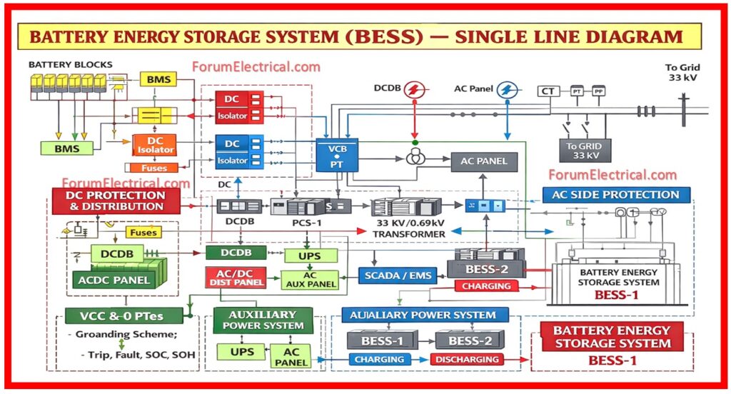
A Battery Energy Storage System (BESS) Single Line Diagram (SLD) is a core engineering document that defines the entire electrical topology, protection philosophy, control interfaces and power flow paths of the grid connected energy storage plant.
- Purpose
- Components in BESS SLD
- 1). Battery Racks / Battery Blocks (DC System)
- 2). Battery Management System (BMS) Integration
- 3). DC Protection & Distribution
- 4). Power Conversion System (PCS)
- 5). Charging and Discharging Power Flow
- 6). AC Side Protection System
- 7). Auxiliary Power System
- 8). SCADA / EMS Interface
- 9). Transformer & MV Grid Interconnection
- 10). Safety, Selectivity & Compliance
- Why SLD is important BESS?
- Conclusion
For utility-scale and industrial BESS the SLD acts as the technical specification for design, approvals, construction, testing, commissioning and long term operation.
Purpose
The BESS SLD provides a clear & standardized representation of how electrical energy flows:
• From battery cells → grid during discharge
• From grid → batteries during charging
It also establishes:
• Protection coordination,
• Safety and isolation philosophy,
• Interface points for SCADA / EMS &
• Compliance with grid codes and standards.
Components in BESS SLD
1). Battery Racks / Battery Blocks (DC System)
• Individual battery cells that is grouped into modules.
• Modules is get assembled into racks.
• Racks connected in series/parallel to form the battery strings.
• Nominal DC voltage levels is typically:
> 750 V DC
> 1000 V DC
> 1500 V DC (utility scale)
SLD shows:
• String configuration,
• Voltage and current ratings &
• Isolation points for each rack/string.
2). Battery Management System (BMS) Integration
The BMS is the primary source of the battery system.
Functions shown in SLD:
• Cell voltage & temperature monitoring,
• SOC / SOH calculation,
• Protection interlocks (OV, UV, OT, OC),
• Trip signals to DC contactors & PCS and
• Communication with PCS & EMS.
Interlocks ensure:
• PCS cannot operate if the battery parameters are unsafe and
• Automatic shutdown during the fault conditions.

3). DC Protection & Distribution
A highly secured DC protection scheme is essential due to the high fault energy.
Primary elements in SLD:
• DC fuses at rack/string level,
• DC isolators for maintenance,
• DC contactors / breakers &
• DC Distribution Board (DCDB)
• DC grounding / earthing scheme which include different categories:
> Ungrounded (floating),
> Mid-point grounded &
> High-resistance grounding.
The fast fault isolation is with proper selectivity and personnel safety.
4). Power Conversion System (PCS)
The PCS is capable of doing energy conversion in both directions.
Functions:
• During discharge, DC is converted into AC,
• In the process of charging, AC converts into DC,
• Grid as a synchronization mechanism &
• A control system for reactive power and power factor.
This includes SLD:
• (kW / kVA) rating for the PCS,
• Connection to the DC input,
• Breaker for the AC output &
• Security and command and control interfaces.
5). Charging and Discharging Power Flow
In a well-designed SLD, the following differences are made:
Grid → Transformer → Power conversion system → Battery for charging
The route for discharging is as follows: battery, power supply, transformer and grid.
It is essential to have this understanding for:
• The coordination of relays,
• Logic development for the EMS &
• Understanding of the operator.
6). AC Side Protection System
On the AC side the SLD includes:
• ACB / VCB at PCS output
• Protection relays are with:
> Overcurrent relays
> Earth fault relays
> Reverse power relays &
> Anti-islanding relays
• Under/over voltage & frequency
• Protection philosophy ensures:
• Grid code compliance
Fault isolation is without any cascading outages
7). Auxiliary Power System
Auxiliary systems maintain the BESS operational even during any outages that is shown in SLD:
• AC auxiliary transformer
• AC distribution panel
• DC panels (110 V / 220 V DC)
• UPS system that consist of for:
> BMS,
> PCS controls &
> SCADA & communication.
8). SCADA / EMS Interface
The SCADA / EMS is the control and monitoring layer.
SLD is used to represents:
• Communication links (Ethernet / fiber)
• Data exchange points
• Control commands:
> Start/stop
> Charge/discharge scheduling
> Power setpoints
This enables:
• Peak shaving,
• Frequency regulation,
• Load balancing and
• Renewable integration.
9). Transformer & MV Grid Interconnection
For utility scale systems the SLD is used shows:
• Step-up transformer (e.g: 0.69 kV / 33 kV)
• MV switchgear
• Protection relays
• Metering panels
• Utility intertie point
This section is very important for utility approval.
10). Safety, Selectivity & Compliance
An appropriate BESS SLD indicates compliance with the following:
• IEC standards,
• IEEE standards &
• Local grid codes (power grid code) and fire safety regulations.
Safety features include:
• Emergency shutdown logic,
• Fire alarm interlocks,
• Mechanical & electrical isolation &
• Proper earthing.
Why SLD is important BESS?
A BESS SLD ensures:
• Safe operation of the batteries and power electronics.
• Reliable grid synchronization and also used for protection coordination.
• Smooth commissioning and testing purpose.
• Clear O&M procedures for the technicians.
• Scalability and long term performance.
Without any SLD even high-quality equipment can fail due to poor integration and proper protection gaps.
Conclusion
The Battery Energy Storage System (BESS) Single Line Diagram is is a strategic engineering document that is used to unifies electrical design, safety philosophy, control logic and grid compliance.
For every utility scale BESS project the SLD is the foundation on which reliability, safety and performance are developed.

 Single Line Diagram is used to explaining DC, PCS, AC protection, SCADA, transformer and also grid interconnection for utility-scale systems.)