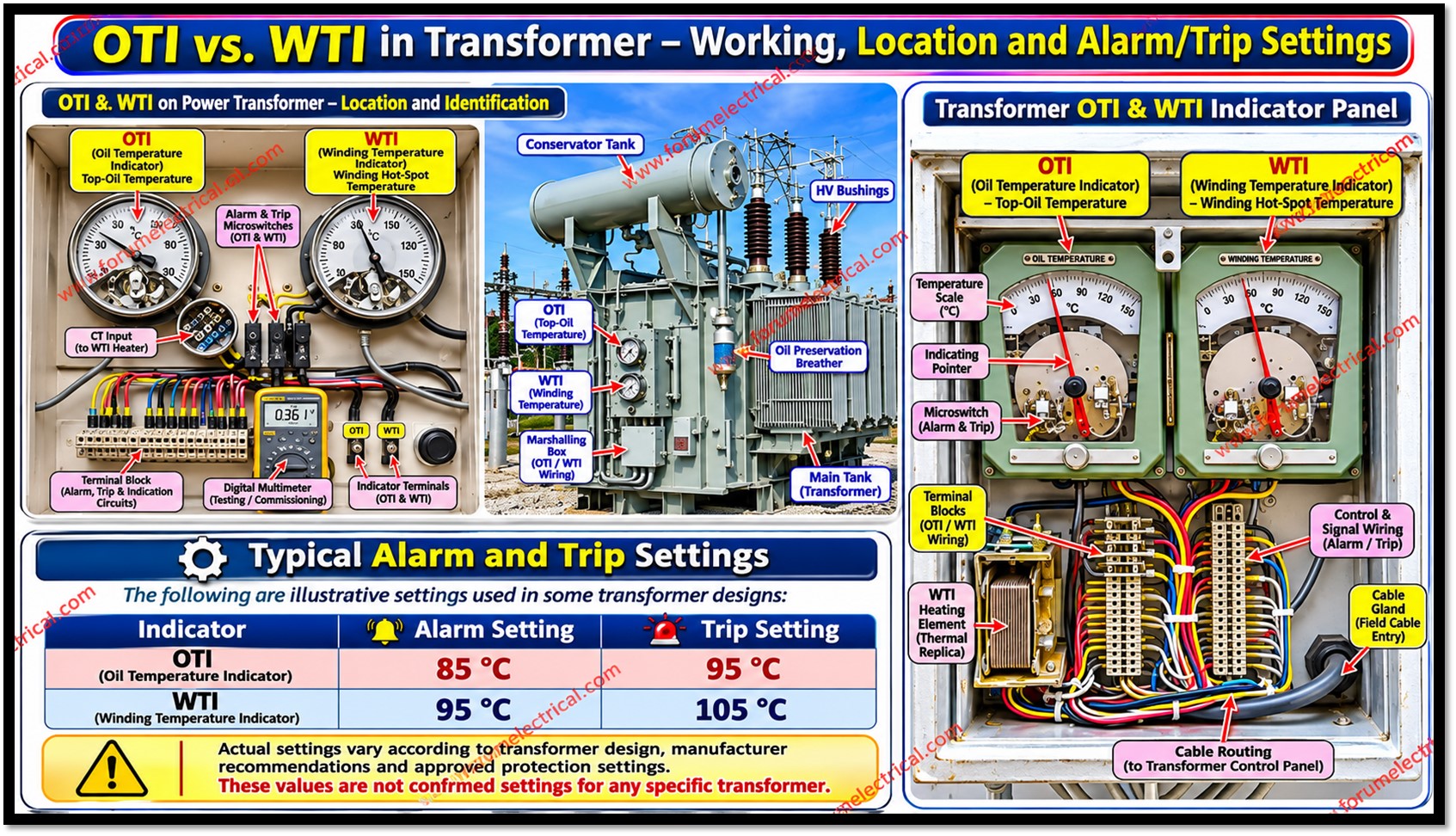
Temperature is a key indicator of the operating condition and aging rate of an oil-immersed power transformer.
Excessive heat accelerates deterioration of solid insulation, reduces service life and, under severe conditions, can contribute to gas generation and loss of dielectric strength.
2 common local instruments used to supervise this condition are:
- Oil Temperature Indicator (OTI) and
- Winding Temperature Indicator (WTI).
They are complementary instruments:
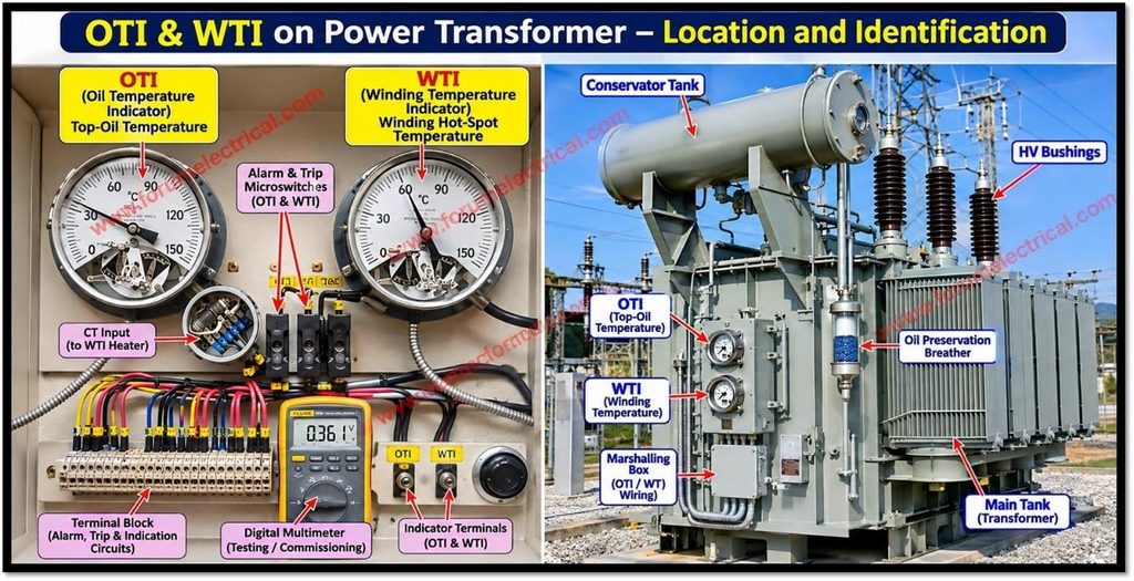
OTI indicates top-oil temperature while WTI estimates the winding hot-spot temperature.
Oil Temperature Indicator (OTI)
The OTI measures the temperature of the transformer’s upper oil region, normally through a sensing bulb installed in a thermometer pocket at the top of the tank.
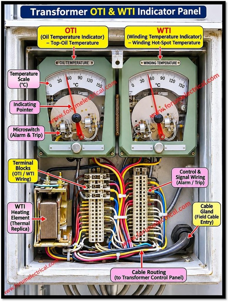
In many traditional instruments, the bulb is connected to a dial mechanism by a capillary tube containing a temperature-responsive fluid.
As the oil temperature changes, the sensing system moves the pointer on the calibrated dial.
Electronic versions may use resistance or other sensing technologies and provide analogue or digital outputs.
Depending on the specified design, OTI contacts can operate alarms, initiate a trip (or) control cooling equipment such as radiator fans and oil pumps.
The OTI therefore gives operators a direct indication of bulk top-oil thermal condition and helps identify abnormal cooling performance, sustained overload, high ambient temperature or restricted oil circulation.
It does not directly measure the hottest point inside a winding.
Winding Temperature Indicator (WTI)
In conventional oil-filled transformers, a dial-type WTI generally estimates winding temperature using the thermal-image (thermal-replica) principle.
A temperature-sensing bulb is commonly placed in an oil pocket, while a heater or image coil inside the instrument produces an additional temperature effect.
A current transformer (CT) associated with the transformer winding supplies a current proportional to load current to the heater circuit.
The heater input is arranged so that its heating effect represents the additional winding temperature rise above the surrounding oil.
The instrument combines the measured oil temperature with this load-dependent heating effect.
Its calibration is intended to approximate the winding hot-spot temperature for the particular transformer design and specified CT/heater arrangement.
The WTI is therefore an estimate, not normally a direct measurement of the hottest conductor point.
Modern fibre-optic probes or other embedded sensors can provide direct local measurements where fitted; these should not be confused with a conventional thermal-replica WTI.
Why does WTI normally read higher than OTI?
Heat must pass from the conductors and insulation into the surrounding oil and then to the cooling surfaces.
Consequently, the winding temperature is normally above the adjacent oil temperature.
The hottest winding location can also be warmer than the average winding temperature because of local current density, stray losses and oil-flow distribution.
A useful conceptual relationship is:
Winding hot-spot temperature ≈ Top-oil temperature + Hot-spot temperature gradient.
The gradient varies with load, transformer design, cooling mode and transient conditions.
The WTI thermal replica attempts to reproduce this load-dependent gradient.
At very light load the difference may be small; as load increases, the WTI indication will generally rise more rapidly than OTI.
A WTI reading is not guaranteed to be higher in every operating or instrument-fault condition.
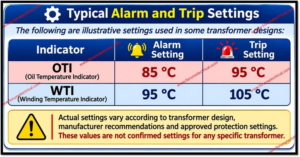
Typical Alarm and Trip Settings
The following values are illustrative examples only.
They are not universal IEC or IEEE limits and must not be copied into a protection scheme without checking the transformer rating, insulation system, cooling arrangement, manufacturer’s instructions and approved protection philosophy.
| Indicator | Illustrative alarm | Illustrative trip |
| OTI | 85 °C | 95 °C |
| WTI | 95 °C | 105 °C |
Actual settings may be higher or lower, and some schemes use staged alarms, fan/pump control, load reduction or trip logic.
Contact ratings, fail-safe behaviour, hysteresis, time delays and interlocking must also be checked.
A temperature contact should not be assumed to trip the transformer unless the approved wiring and protection drawings confirm that function.
Difference between OTI and WTI
The difference between OTI and WTI are:
OTI vs. WTI
| Parameter | OTI | WTI |
| Primary indication | Top-oil temperature | Estimated winding hot-spot temperature |
| Sensing principle | Oil-pocket bulb / sensor | Oil temperature plus load-proportional heater effect, traditionally |
| Load sensitivity | Responds mainly to oil thermal response | Includes simulated winding heating related to load current |
| Main purpose | Oil and cooling-system supervision | Winding insulation thermal-stress supervision |
| Typical actions | Alarm, cooling control, trip if specified | Alarm, cooling/load control, trip if specified |
Inspection, Testing and Common Failure Points
During routine maintenance, inspect the dial, pointer movement, glass, seals, capillary, sensing pocket, terminal wiring and contact condition.
Confirm that the sensing bulb is correctly seated and that the capillary is not kinked, crushed or leaking.
For a WTI, verify the correct CT ratio, polarity, secondary circuit continuity, heater resistance and specified wiring arrangement.
Never open-circuit an energized CT secondary; isolate and short the CT using approved procedures before working on its circuit.
Functional checks should compare the instrument with a traceable temperature source (or) calibrated reference over suitable points.
Verify alarm and trip contacts by controlled simulation or an approved test method, coordinating with operations to avoid unintended transformer tripping.
A WTI that reads implausibly high or low may have an incorrect CT connection, wrong calibration, failed heater, loose wiring (or) a sensing-system defect.
An OTI discrepancy may arise from a faulty bulb, capillary or dial mechanism. Record as-found/as-left readings and test results.
Standards
- IEC 60076-2 specifies temperature-rise requirements and test methods for liquid-immersed transformers.
- IEEE C57.91-2025 is the current IEEE loading guide for mineral-oil-immersed transformers and step-voltage regulators; it addresses loading, temperature criteria and insulation-life implications.
Conclusion
OTI and WTI provide different but complementary information.
OTI monitors the top-oil temperature and helps assess the overall thermal condition and cooling performance.
A conventional WTI estimates the winding hot-spot temperature by adding a load-dependent thermal replica effect to the oil-temperature measurement.
Since winding insulation is exposed to the winding hot-spot temperature, WTI is particularly important for evaluating thermal stress and loading.
Reliable protection depends on correct instrument selection, calibration, CT wiring, functional testing and settings approved for the specific transformer.

 and Winding Temperature Indicator (WTI) in power transformers including their working principles, functions, temperature monitoring, and protection applications.)