Earthing is a fundamental part of an electrical installation protective system.
It provides a deliberate connection between exposed conductive parts and the general mass of earth and helps establish a path for fault current in arrangements designed to use earth-fault protection.
When a fault occurs, an effective protective arrangement helps limit dangerous touch voltages and enables the relevant protective device to disconnect the supply within the required time.
An earth resistance test checks the resistance associated with an earth electrode and the surrounding soil.
The result is one important part of assessing an earthing system; it does not, by itself, prove that the complete installation is safe.
- Protective-conductor continuity,
- Bonding,
- Loop impedance,
- Protective-device settings and
- Disconnection times may also need verification.
Why Earthing is Important?
- Personnel protection: reduces the risk of hazardous touch voltages when used with correctly designed and maintained protective measures.
- Fault-current path: provides a defined path for earth-fault current, according to the system earthing arrangement.
- Protective-device operation: supports operation of MCBs, MCCBs, fuses and earth-fault protection where the fault-loop impedance and protection design permit.
- Equipment protection: helps protect transformers, motors, switchgear, control panels and other equipment against consequences of insulation failure.
- System reliability: supports equipotential bonding, surge protection arrangements and dependable operation of the electrical installation.
Principle of the 3-Pole Fall-of-Potential Method
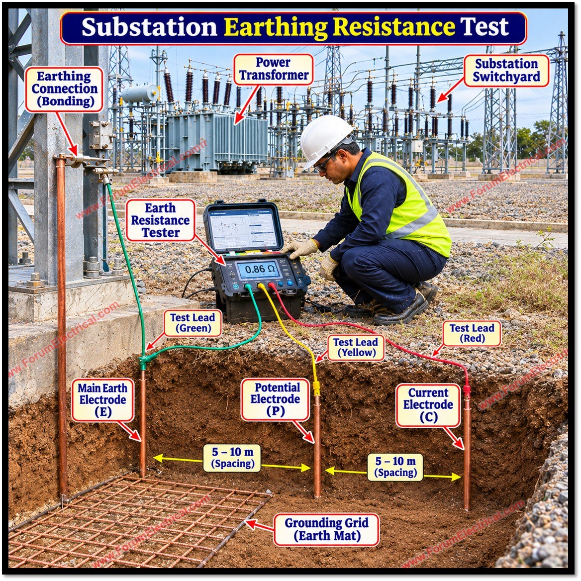
The 3-pole method is a commonly used technique for measuring the resistance of an earth electrode or an electrode system.
A suitable earth resistance tester injects a test current between the electrode under test and a remote auxiliary current electrode.
It measures the voltage between the electrode under test and an auxiliary potential electrode.
The instrument calculates resistance using the relationship
R = V/I
The three principal terminals or connections are:
- E (Earth): connected to the earth electrode or earthing system being tested.
- P (Potential): connected to the auxiliary potential probe. It senses the voltage developed in the soil.
- C (Current): connected to the auxiliary current probe. It completes the test-current circuit.
The auxiliary probes must be positioned so that their resistance areas do not significantly overlap the test electrode’s resistance area.
If they are too close, the measured value can be misleading.
Follow the tester manufacturer’s terminal markings and lead-connection instructions; terminal names and lead arrangements can differ between instruments.
Electrode Positioning and the 62% Rule
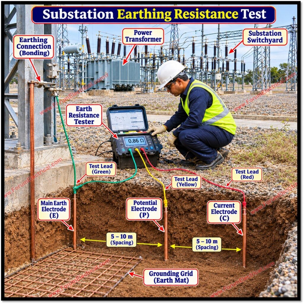
In a typical straight-line test layout, the C probe is driven into the soil at a suitable distance from the electrode under test (E) and the P probe is placed between them.
For a simple electrode in reasonably uniform soil, the potential probe is often positioned at approximately 62% of the E-to-C spacing measured from E towards C. This is known as the 62% rule.
The rule is an approximation, not a universal placement rule. Its reliability depends on the electrode geometry, sufficient separation, reasonably uniform soil and the absence of significant parallel metallic paths or interconnected electrodes.
The original guidance to place C at least five times the largest dimension of the electrode system is a practical starting point in some procedures not a guarantee of adequate separation.
Large grids, extensive buried conductors, layered soil or restricted sites may require greater spacing, multiple directions, a slope method or an engineering assessment.
To check whether the reading is stable, take readings with P at several positions around the nominal point, for example 52%, 62% and 72% of the E–C distance.
Similar readings indicate that the potential probe is likely within a reasonably flat portion of the resistance curve.
Large variation suggests inadequate spacing, soil non-uniformity, interference or another test-layout problem.
Do not simply select the lowest reading.
Testing Procedure
- Review the approved method statement, site risk assessment, earthing drawings and acceptance criteria. Identify the electrode or grid section to be tested.
- Assess whether isolation or disconnection is necessary. Where the electrode must be separated from parallel earth paths to obtain an individual electrode result, do so only under an approved safe system of work. Never remove a protective earth from energized equipment without an approved isolation and risk-control procedure.
- Confirm that the earth resistance tester is suitable for the application, within calibration, undamaged and operated in accordance with its manual. Inspect test leads, clips and probes for damage.
- Select a test direction clear of buried services, fences, pipes, cable sheaths and other metallic structures. Check underground-service information before driving probes.
- Install the C probe at the planned remote distance and connect the E, P and C leads to their corresponding terminals. Keep leads separated where practicable and avoid routing them alongside power cables.
- Place the P probe initially at approximately 62% of the E–C distance. Ensure firm soil contact; moisten very dry soil around a probe only if the approved procedure and instrument guidance permit it, and record the action.
- Operate the tester using the specified test mode. Observe any noise, auxiliary-electrode resistance or interference warnings displayed by the instrument.
- Move P to additional positions, such as 52% and 72%, and repeat the measurement. If results vary materially, investigate the layout and repeat with greater C spacing or an alternative approved method.
- Record the measured resistance, probe spacing and direction, instrument identification, calibration status, date, soil and weather conditions, and any limitations or parallel connections.
Interpreting Results and Reference Values
A lower measured electrode resistance generally indicates a more conductive connection to the surrounding soil but the acceptable value depends on the
- Installation type,
- Earthing design,
- Supply arrangement,
- Protective-device characteristics,
- Soil conditions and
- Applicable regulations.
The test result must be assessed against the project specification and the governing standard not against a single value assumed to apply to every site.
| Installation Category | Commonly Quoted Reference Value |
| Large power stations | 0.5 Ω |
| Major substations | 1 Ω |
| Minor substations | 2 Ω |
| General installations | 8 Ω |
These figures are frequently regenerated as indicative values associated with older guidance including references to IS 3043:1987.
They should not be presented as universal statutory limits or automatic pass/fail criteria.
Confirm the exact requirement in the applicable edition of IS 3043, relevant regulations, approved design documents and client specifications.
Different systems such as TT, TN and installations with extensive interconnected earth grids are assessed using different design and protection considerations.
Common Sources of Error and Troubleshooting
- Insufficient probe spacing: increase the E–C distance and repeat the potential-probe position checks.
- Poor probe contact or very dry ground: improve probe contact using the method permitted by the tester manufacturer and document any treatment.
- Parallel earth paths: interconnected electrodes, cable sheaths, structural steel and buried services can influence the result. Determine whether the test is intended to measure an individual electrode or the connected system.
- Electrical noise or induced current: move test leads away from energized conductors where possible, use the instrument’s noise-rejection facility and follow safe site procedures.
- Non-uniform or layered soil: repeat in another direction or use a suitable alternative test arrangement interpreted by a competent person.
- Unstable readings: check terminal connections, lead continuity, probe positions, instrument warnings and the adequacy of the test distance.
Safety Precautions
- Check for buried electrical cables and other services before inserting auxiliary probes.
- Treat earthing conductors and electrodes as potentially carrying hazardous current, including diverted neutral or fault current. Use appropriate PPE and follow the approved risk assessment.
- Do not perform a test during lightning risk or under unsafe weather/site conditions. Follow instrument limits and manufacturer instructions.
Final Verification and Test Report
Before accepting the result, the supervisor should verify that the correct electrode (or) grid section was tested, the test arrangement was suitable, the instrument was calibrated, the probe positions were adequate and repeat readings were reasonably consistent.
Any unexplained variation or result outside the approved criterion must be investigated and documented before commissioning or handover.
A complete record should include the equipment or electrode identification, location, test method, E–P and E–C distances, test direction, readings at each P position, final reported value, instrument make/model and serial number, calibration details, date and time, soil condition, recent weather, isolation or disconnection details, connected parallel paths, test limitations, acceptance criterion and the names/signatures of the tester and reviewer.
Summary
The 3-pole Fall-of-Potential method is a practical and widely used way to measure earth electrode resistance when the test geometry and site conditions are suitable.
Reliable results depend on adequate auxiliary-electrode spacing, correct connections, repeatable potential-probe readings and careful consideration of parallel paths and soil conditions.
A resistance value should always be interpreted within the complete earthing and protective-disconnection design.
Accurate records and competent review are essential before commissioning and handover.

