
- What is Earth Fault Loop Impedance Test?
- Why to do Earth Fault Loop Impedance Test?
- What is the process of Earth Fault Loop Impedance Testing?
- How should an Earth Fault Loop Impedance test be carried out?
- External Earth Fault Loop testing procedure
- Test Sequence for the Earth Fault Loop
- Methods for Loop Impedance Tests
- Impedance Value
- Summary
What is Earth Fault Loop Impedance Test?
An earth fault loop impedance test ensures that, in the case of an electrical failure, there is enough current to operate the fuse (or) circuit breaker that protects the defective circuit. Circuits frequently overheat & even catch fire if a “fault current” goes unchecked.
Why to do Earth Fault Loop Impedance Test?
Every circuit must be examined to ensure loop impedance does not exceed protective device specifications. Earth fault loop impedance testing is essential for
- Electrical installations and
- Power outlets
due to the severity of electrical faults.
The equipment and circuits are important to the company’s longevity and operation. The majority of residences use an earthing circuit with automated switches in interior wiring circuits for shock safety. If a fault occurs and interface voltage exceeds a permissible level, this instantly turns off earthing circuit supply.
Current national safety rules demand loop impedance testing on the premises to protect visitors and staff. Test the electrical earth of all the electrical installations & power points to find circuit complications.
A working earth return circuit allows the MCB to detect circuit failures and react. If the earth return circuit resistance is too high, tripping alerts.
Follow national laws to avoid heavy fines.TN/TT installations and protection types such
- Miniature circuit breakers (MCBs),
- Cartridge fuses, and
- Re-wireable fuses
affect impedance and time requirements.
The fault current may be in the Line-Neutral (or) Line-Earth circuit, thus the loop impedance of each must be tested.
NOTE:
- TN – Transformer Neutral Earthed, Frame connected to Neutral.
- TT – Transformer Neutral Earthed & Frame Earthed.
What is the process of Earth Fault Loop Impedance Testing?
It is generally accepted that where a circuit’s measured earth fault loop impedance is less than 80% of the relevant limit specified in BS 7671 [circuits supplied at nominal voltages up to & including 1000V AC (or) 1500V DC], the impedance can be expected to be sufficiently low under earth fault conditions to meet the relevant limit specified in BS 7671& for the protective device to automatically disconnect in the time specified.
When the TT wiring system complies with the following requirements, it provides adequate protection from electric shock hazards:
Ra x Ia< 50
Where,
Ra – Total of the earth bar and protective conductor resistances and
Ia – Protection system maximum current.
Ra multiplied by Ia must not exceed 50 V, indicating that the greatest voltage one can contact in the case of an earth fault will not go above 50 V. Between the active conductor & the ground, a fault loop impedance test is performed.
To test the loop impedance, the technician utilizes an earth loop impedance tester that is hooked into a power socket (GPO).
How should an Earth Fault Loop Impedance test be carried out?
The External earth loop impedance (Ze) test is the one that need to be performed first. The circuit loop impedance, excluding the installation, may be determined using this test, which is carried out at the distribution board.
The following step that has to be done is the system loop impedance test, also known as Zs. This test takes into consideration both the installation resistance and the circuit that was examined during the Ze test. It is possible for the AC impedance of a circuit to deviate from its DC resistance; this is particularly prevalent for circuits rated at more than 100 A.
Because of this, the fault loop impedance is measured utilizing the same frequency as the nominal frequency of the mains, which is 50 Hz.
The Ze earth fault loop impedance test is performed on the supply side of the distribution board and the primary method of earthing. The main switch should be open and all circuits should be isolated prior to doing this measurement.
During the test, the process of earthing will be separated from the bonding of the installation’s earthing system (also known as earth rods). The earth fault loop impedance will be confirmed as the total of the resistances after the Ze measurement has been completed.
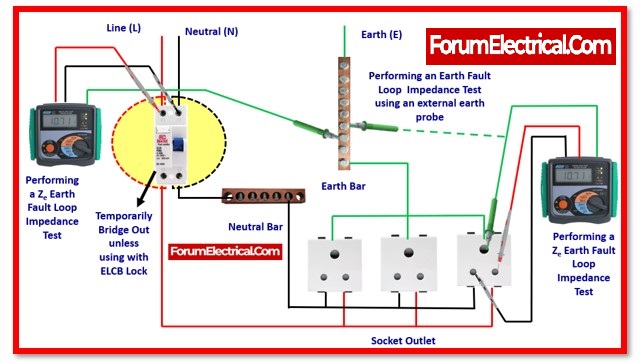
External Earth Fault Loop testing procedure
Step 1: Use an Earth Fault Loop Tester (or) the Earth Fault Loop Test feature on a multifunctional tester like the Megger.
Step 2: Run a test on the installation’s incoming side. Connect one test lead to Line terminal, one to the Neutral terminal, and one to the incoming Earth conductor (typically green).
Do not forget to enter this ‘Ze‘ value on the electrical Installation certificate.
Step 4:Once the ‘Ze‘ value has been determined for the installation, the value of ‘Zs‘ may be readily computed for each circuit.
Step 5: Irrespective of the requirements of the relevant protective device(s), the maximum number of measured earth fault loop impedance (Zs) values should be consistent with the Ze + R1 + R2 value of each circuit.
Step 6: Low current test results are not reported on test result schedules; instead, the Zs values generated from individual test results should be recorded.
Zs may be calculated using the following formula:
Zs = Ze + (R1 + R2)
Zs– earth fault loop impedance of the tested circuit
ze– External supply earth fault loop impedance
(R1+R2)- The sum of the resistances of the tested circuit’s line and earth.
Where,
Ze is the result of a high current test &
R1 + R2 acquired during circuit continuity testing.
The test results must be recorded & the test method utilized will be stated.
The impedance of the Zs earth fault loop is measured at the furthest point in each circuit. Most of the time, the circuit breaker must be bridged out.
The total earth fault loop impedance is determined by inserting a loop tester into a socket outlet or, in rare conditions, by using an external earth probe. The total of the resistances is the measurement of the earth fault loop impedance.
The earth fault loop impedance is determined using an external earth probe by contacting it directly to an earth bar, collector, and connecting point of an earth bar.
Connecting the earth probe to exposed, conductive elements of equipment in circuits and exposed metal parts provides the same result.
Test Sequence for the Earth Fault Loop
Step1: Locate the circuit’s furthest point (such as its furthest socket).
Step 2: Attach the test leads to the Line, Neutral, and Earth terminals using an appropriate Earth Fault Loop Tester.
Step 3: Measure the test findings and record them on a Schedule Of test findings.
Step 4: If the circuit is RCD protected, must choose the “No trip” feature of the Megger to stop the RCD from accidentally tripping.
Step 5: It is necessary to connect out the RCD if megger doesn’t come with this option.• After obtaining the Zs value for each circuit, will be required to confirm that these values fall within the permitted ranges specified by BS 7671.
Methods for Loop Impedance Tests
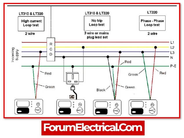
When doing loop impedance testing, the majority will use one of five test methods:
- 2-wire high current test
- 2-wire“No-Trip” dc saturation test
- 3-wire“No-Trip” test
- 2-wire“No-Trip” test
- 4-wire grid impedance test
2-Wire High Current Test
This is the standard loop impedance test. It is by far the fastest and most accurate test accessible on a daily basis, with a test current of up to 20 A & a simple two-wire connection. This type of test is included in the majority of conventional loop impedance testers. Because of the relatively high-test current, the measurements are largely unaffected by external variables and will provide repeated, steady results in most conditions.
2-Wire“No-Trip” Dc Saturation Test
The circuit was tested with a DC test current before a typical 2 wire high current test was performed. The purpose of this DC test was to totally saturate monitoring coil within the RCD so that the high current AC test could be completed. However, this method only has a limited number of uses currently because to the increasing number of electronic RCDs.
3-Wire“No-Trip” Test
This test method used a low current Line-Earth test current to by-pass even the newest electronic protection systems while still providing some accuracy. A time saving element was certainly added by not needing to bypass the RCD/RCBO. The testers were also able to validate the presence of all three by connecting to Line, Neutral, and Earth. They could also now indicate whether there was reverse polarity at the test point, and because the test current was limited, there was no possibility of triggering the MCB.
2-Wire“No-Trip” Test
Most RCDs & RCBOs may be tested with them without needing to be bypassed. They continue to function as an authentic 2-handed device without the need for a neutral connection, but they no longer signal reverse polarity or generate a neutral connection warning. However, the physical test takes about the same amount of time that the 3-wire approach is doing, the test is more effective since there is no need to bypass the RCD.
4-Wire Grid Impedance Test
The test is accurate because it employs a 4-wire Kelvin connection to eliminate internal lead & contact resistance.
Measurements down to 10 MΩ are accurate with test currents reaching 1000 A.
No “No-Trip” option is available with this test method.
This tester enables test engineers collect reliable measurements in sub-station/switch room conditions.
A circuit protected by an RCD requires special care because the earth-fault loop test draws current from the phase that returns via the protective device.
Thus, instrument developers have attempted to provide test findings equivalent to those of non-RCD-protected circuits without tripping the RCDs. Before earth-fault loop testing, RCDs must be short-circuited. The primary objective is to eliminate such connections after testing.
The test outcome depends on supplied voltage, therefore slight changes effect it. Therefore, the test must be done numerous times for consistency.
Anyone on location must avoid shock during contact and testing. When acquiring a loop tester, request distribution board test leads for Ze and Zs readings.
Impedance Value
Testing and recording of earth fault loop impedance testing is often performed on a completed electrical system to ensure conformity with BS 7671 (IET Wiring Regulations) in terms of fault prevention.
1. With a test current of around 23A, where circuits are simply protected by the overcurrent devices such as fuses or circuit breakers.
(or)
2. With a test current of around 15mA, to prevent tripping in circuits protected by 30mA (or) other RCDs. Typically, high current (23A) test results in a range of 0.1Ω to 1.0Ω are essentially constant with an accuracy of 0.01. The level of accuracy for low current (15mA) testing was 0.1Ω, but measures to reduce this to 0.01Ω have been mainly ineffective in delivering reliable findings for values less than 1.0Ω.
Summary
Earth fault loop impedance testing ensures a secure ground connection with minimal residual resistance. If a live wire is incorrectly linked to an earth conductor in a malfunctioning appliance or circuit, the short-circuit current to the earth can be large enough to cause electric shock or a fire. Earth loop impedance testing is necessary.
The fuse will blow (or) another circuit protection device will trip, but a poor installation may have inadequate short-circuit current, causing the protection device to take too long to activate. Delays may ruin lives and property.
Therefore, it is essential to understand if the fault current impedance transmit is low enough to enable adequate current to flow in the case of a problem and if any fitted protective device would work safely.
