
What is the PLC Timer?
PLC timers are instructions used in ladder logic programming. When applied to a ladder diagram, it causes a time delay if a specific event happens. A basic PLC timer consists of
- Start input,
- Preset time input, and
- Done output.
It is essential to realize that a PLC timer command causes a time delay that only impacts the execution of the timers’ outputs.
The PLC scan is not immediately delayed; it continues to scan all of the ladder logic rungs as normal.
The PLC timer mimics the functionality of traditional timer relays.
Initially, timer relays were used in relay logic circuits & were mechanical.
Mechanical timer relays were eventually superseded by electronic timer relays, and they are currently used as software timers in PLCs.
Basic Internal Circuit of PLC Timer
The timer circuit consists of four major components.
Each internal component of the timer circuit has different properties and functions.
Here are some basic terms you should be familiar with when it comes to PLC timers.
- Input & Output Modules
- Power Supply Module
- Internal Timer Circuit
- Timer Digital Display
Input & Output Modules
Input Module: The module that interacts with the input signal is known as the Input Module. The input module must be connected to the timer circuit before it may provide the input signal.
Output Module: The module that interacts with the output signal is known as the Output Module. The output module is necessary for connecting the timer circuit.
Power Supply Module
The power module supplies power to the timing circuit, allowing it to function properly. It can connect to either an alternating current (AC) voltage source (120, 230 V AC) or a direct current (DC) voltage source (5, 12, 24 V DC).
Internal Timer Circuit
The timer circuit handles the set & reset functions.
If the auxiliary power supply is ‘ON’, the timer will send a momentary input pulse for the set and reset operations.
Timer Digital Display
The digital timer displays both the set & elapsed timing values.
For automated purposes, the values can be shown in a few milliseconds. This will make it easier to track your automation system.
Types of PLC Timer
The PLC programming timer is classified for ladder diagram programming as:
- On Delay Timer (TON)
- Off Delay Timer (TOFF)
- Retentive ON/OFF Timer (RTO)
- Pulse Timer
On Delay Timer (TON)
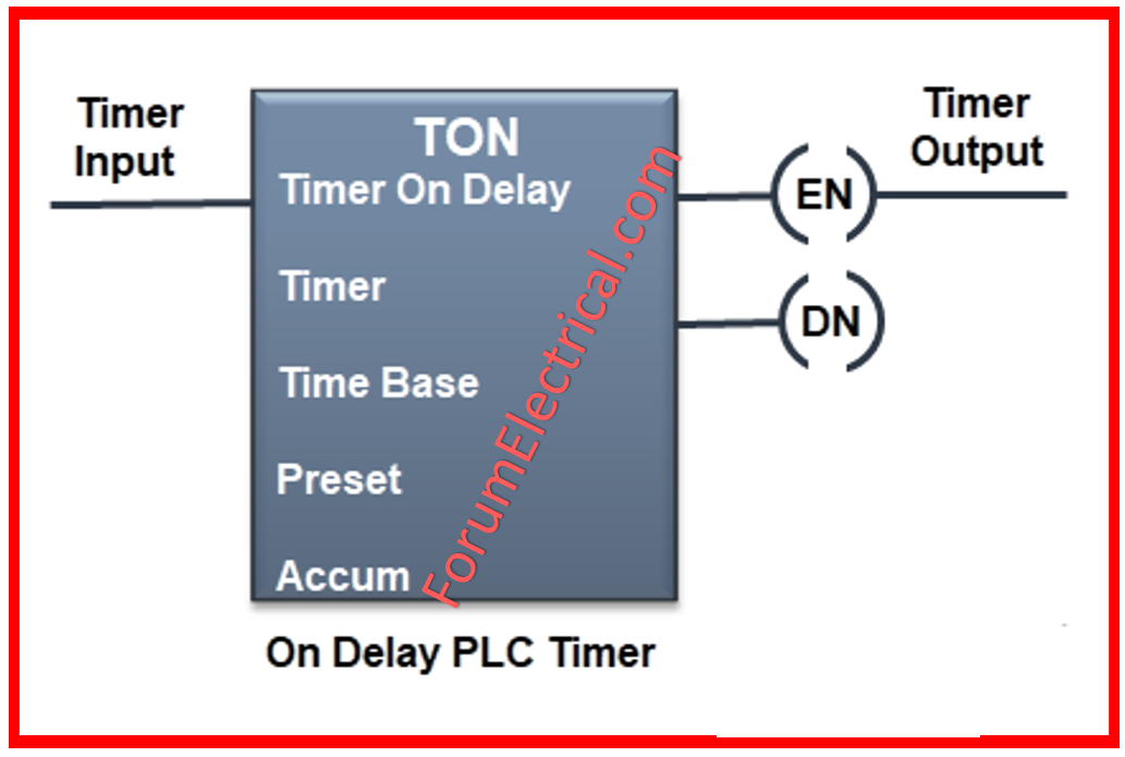
An on-delay timer (TON) is a programming command that initiates brief pulses for a specified amount of time.
The output of the ON Delay Timer (TON Timer) is not activated until a predetermined amount of time has passed. In simple terms, the output is postponed until it activates.
Function
An ON delay timer in a PLC is designed to keep attention on a specific input, add a delay, and then activate an action (output) once the delay has passed.
You can configure the time delay using the input, and turning off the input resets the output.
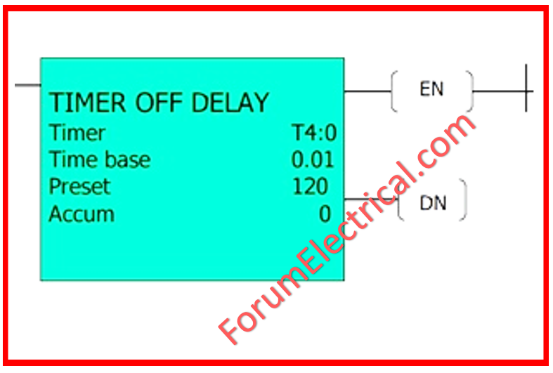
Off Delay Timer (TOFF)
An off-delay (TOF) timer is a PLC programming instruction that turns off an output or system after a set length of time.
The OFF delay timer’s operation is a direct reflection of the name of the device themselves.
The OFF Delay Timer, also known as the TOF Timer, is designed to only turn its output off after a predetermined amount of time has passed.
The output is DELAYED prior to it turns off, to put it another way.
Function
An OFF delay timer in a PLC monitors the occurrence of a certain event (input) & promptly initiates an action (output).
Then, waiting for the input to turn off, add a time delay, and finally reset the output. The delay time is adjusted using the preset time input.
Retentive ON/OFF Timer (RTO)
The primary function of the RTO is to hold (or) store the set (accumulated) time.
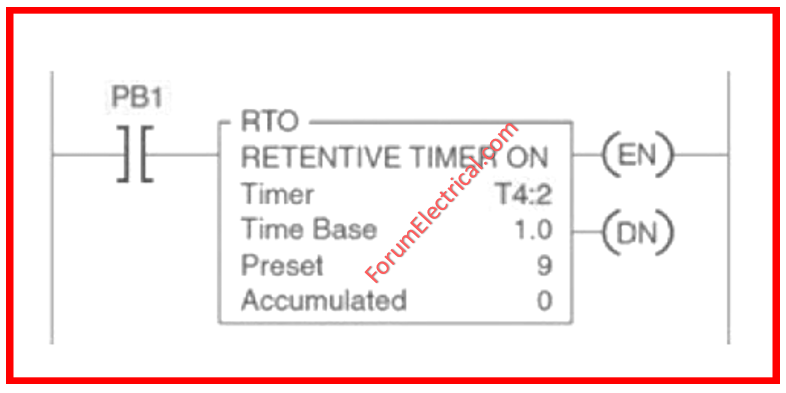
RTO is utilized when the rung status changes, there is a power outage, or the system is interrupted.
The Siemens PLC is the only one with the Retentive ON Delay Timer. The Retentive ON Delay Timer in Siemens PLCs is referred to as S_ONDTS timers (Retentive ON Delay S5 Timer).
Because it only activates its output after a predetermined time DELAY, the Retentive ON Delay Timer functions similarly to the ON Delay Timer. Nevertheless, the timer restarts if the start input is triggered again while it is still running. The output may only be reset by activating the reset input.
Function
A Retentive ON Delay Timer in a Siemens PLC is designed to keep the output turned on even if the input is turned off.
It does this by monitoring the occurrence of an event (the input) and adding a delay to it. Resetting the output is as simple as pressing the reset input.
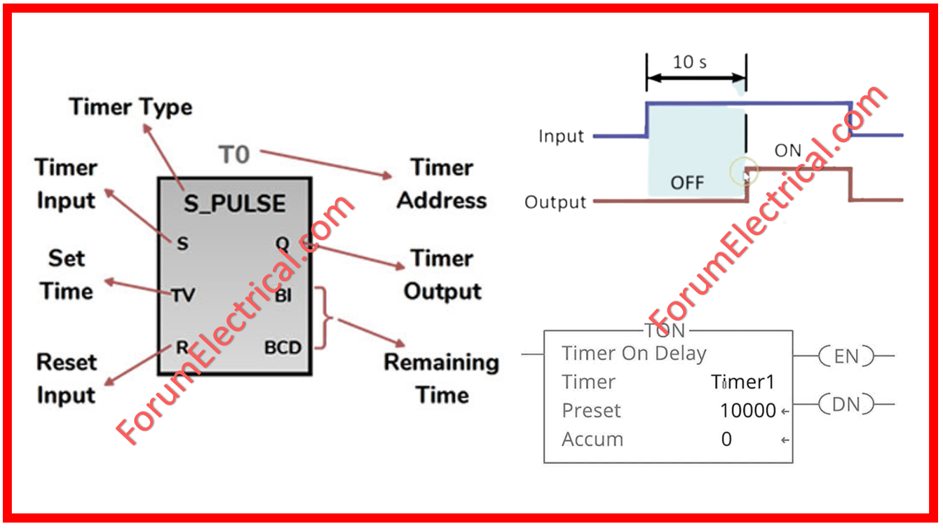
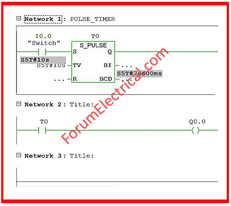
Pulse Timer
The PLC Pulse Timer is another prevalent timer used in PLC programming. It is one of three PLC timers specified in the IEC 61131-3.
In a PLC, the Pulse Timer is frequently referred to as a PT timer.
The Pulse Timer generates an output PULSE with the pulse duration equal to the preset time value. The TP timer output is “ON” when the timer is operating and OFF at all other times.
Function
Upon the input changing from FALSE to TRUE, a PLC pulse timer starts functioning.
The timer starts to count down once the output is activated. The output is disabled once the timer goes off. So, a pulse is generated with a duration matching the timer’s set value.
Timer Instructions Address for Different PLC Brands
We’ve seen 4 timers providing time delay functionality for PLC operations. The timer deals with four primary values.
- Timer Address
- Preset Value
- Timer’s Base Value
- Accumulated Value
Each timer instruction contains three extremely useful status bits. These bits are
- Enable Bit (EN)
- Timer Timing Bit (TT)
- Done Bit (DN)
In the ABB & Siemens PLC, the output bit is commonly referred to as the timer’s ‘Done bit’.
And it signifies that the timer has attained its programmed time.
Applications of Timer Instruction
Here are some basic timer applications for utilization in a PLC automation setting.
- Use for delaying action.
- It is utilized to run (or) stop operations according on the user’s commands.
- The RTO timer is useful for recording or storing intermediate time values.
What is EN and ENO in PLC?
You have chosen a function block. To activate the function block, simply add the input EN.
What is FB in PLC?
When a function block (FB) calls another FB, the data from the calling FB’s instance database can be kept.
This type of block call is known as a multi-instance block call. Build a “Use case” function block.
Difference between a TON and TOFF Delay Timer
| TON Delay Timer | TOFF Delay Timer |
| Upon input activation, the TON timer delays the output’s turning ON. | TOFF timer delays the output’s turnoff from when the input’s turnoff occurs and switches the output ON instantly upon input turnoff. |