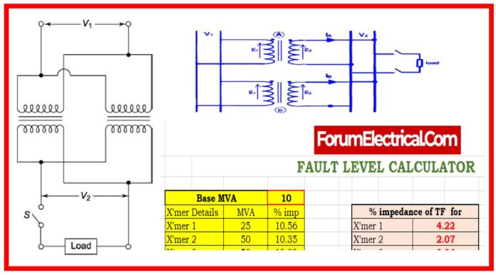
Fault level calculation is an important step in ensuring the safety & reliability of an electrical system.
Calculator
It involves assessing the potential short-circuit levels at various locations in the system, usually on a high-voltage (HV) bus, which helps to design and safeguard equipment appropriately.
When numerous transformers are utilized in parallel to distribute load throughout the system, the procedure becomes more complex.
Transformer Information
The system’s transformers are identifiable by their MVA (Mega Volt Amperes) ratings and % impedance.
These values are critical parameters in fault level calculation because they affect the amount of fault current that flows in the case of a short circuit.
Formula to calculate Transformer Impedance (Z%)
ZTF = (Z%/Base MVA) X Transformer MVA
Where
Z% – Transformer Impedance Percentage
Base MVA – System Base MVA (Ex: 10 MVA)
Transformer MVA – Individual Transformer MVA Rating
Fault Level on High Voltage (HV) Bus
Fault levels are commonly estimated for a system operating on a high-voltage bus in both single-phase and three-phase modes.
Single-phase faults are often smaller in scale but can still cause substantial problems, whereas three-phase faults are typically the worst-case situation for fault current magnitude.
Parallel Operation of Transformers
When transformers are run in parallel, the system’s overall impedance varies, influencing the fault level.
Transformers can be connected in parallel to improve capacity and better distribute load.
The computation for parallel operation varies according to whether one, two, or three transformers are connected.
1/ ZParallel = 1/Z1 + 1/Z2 + 1/Z3+…
Single Transformer in Parallel
In a system with a single transformer running in parallel, the total parallel impedance is determined using the transformer’s percentage impedance. This value is essential for calculating short-circuit (SC) MVA on the transformer’s low voltage (LV) side.
ZTotal = ZTF1 + ZSource
Two Transformers in Parallel
When two transformers run in parallel, the total impedance of the system is lowered. The lowering in impedance has a direct impact on the fault level, increasing short-circuit MVA.
ZParallel= Z1 x Z2/Z1 + Z2
This is due to shared load capacity and lower resistance to fault currents.
ZTotal = ZParallel + ZSource
Three Transformers in Parallel
With three transformers linked in parallel, the system’s total impedance changes again, usually reducing more, resulting in an even greater fault level.
1/ ZParallel =1/Z1 + 1/Z2 + 1/Z3
The short-circuit MVA is recalculated to ensure that the system can safely handle any potential fault currents.
ZTotal = ZParallel + ZSource
Source Impedance and Total Impedance to LV Bus
The source impedance, or the impedance from the energy source to the HV bus, is critical for failure level calculations.
This impedance, together with the parallel transformer impedance, forms the total impedance of the low-voltage (LV) bus.
The total impedance affects the total fault level for both single-phase & three-phase failures, and it must be carefully considered for successful system design and protection.
Short-Circuit MVA Calculation
The short-circuit MVA (SC MVA) is calculated as the product of voltage and fault current, and it represents the potential power involved in a failure.
This value must be determined for each case: single, two, & three transformers in parallel.
These calculations are critical for estimating the needed ratings of circuit breakers & other safety equipment in the system.
SC MVA = Base MVA/ ZTotal
Conclusion
Fault level calculation is an important aspect of electrical system design, especially when numerous transformers are coupled in parallel.
Engineers may protect the system from potential faults by estimating the impedance & short-circuit MVA for each configuration.
This protects both equipment and workers.
Click here for more Electrical Calculators


