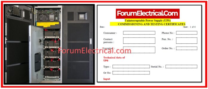
UPS Commissioning and Testing Certificate
This certificate is a detailed guide to checking out and testing an Uninterruptible Power Supply (UPS) system.
The technique assures safe and efficient operation by covering a variety of topics such as electrical connections, system components, & power configurations.
General Information
This part contains general client information such as the customer’s name, contact details, location, phone number, fax number, and order number.
Technical Data for UPS
The UPS system’s type & serial number should be documented. In addition, the order number must be noted for tracking purposes.
Input Specifications
Before beginning any inspections, ensure the rated voltage and frequency of the UPS input.
Output Specifications
The UPS’s rated voltage, voltage tolerance, rated frequency, & frequency tolerance should all be verified. Its overload capability, as defined by IEC 146, as well as the short circuit current, must be tested.
Unit Specifications
It is critical to ensure that the permissible ambient air temperature and suggested ambient temperature are within acceptable limits for the UPS unit. Furthermore, the degree of protection & humidity class must be validated to match operational requirements.
Power “OFF” Checks
Before turning on the UPS, certain checks must be completed. First, look for loose connections & broken wires in the battery cabinet, UPS, incoming and outgoing cables. Following that, check for any loose components & make sure the wiring fits the diagram. PCB plugs need to be properly placed, and all shields must be properly terminated. It is also essential to ensure that the fuses meet the engineering criteria. Additionally, use an ohmmeter to verify the power rectifier, switching devices, & DC-Link. The power source must be carefully selected based on the system requirements.
System Connections
Following the initial checks, the system must be linked using the diagrams provided. Double-check all connections for faults or loose connections. Ensure that the control system is correctly grounded. The incoming voltage as well as frequency should be confirmed and measured to verify they are within acceptable limits. In addition, each battery’s voltage should be checked.
Check for power “ON” and if the rectifier switch is ON.
Close the incoming breaker & monitor the voltage on the DC bus to ensure system balance.
The logic board’s power supplies should be verified, with the right voltages confirmed for each (including +5Vdc, +15Vdc, -15Vdc, & others). It is critical to inspect and configure the keypad programming & parameters.
Each battery’s floating voltage, and the total battery voltage, must be verified and changed as needed.
Check the rectifier unit card for current limits, voltage settings, & whether the regulator is saturated. In addition, examine the rectifier’s start and stop signals.
Connecting Batteries using DC-Link
After the rectifier has been tested, connect the batteries to the DC-Link. Monitor & measure the voltage of the DC-Link, as well as the current flowing between it and the batteries.
Switch on the inverter
When you turn on the inverter, measure the secure bus voltage & frequency. Adjust the inverter control unit to set the basic frequency, voltage, and current limit.
The DC balance & modulator triangle balance should also be examined. The inverter monitoring unit card should be set to ensure precise monitoring of the output voltage, battery voltage, & other data.
Fan failure, overheating, and frequency failures are all critical inspections.
Static Bypass Switch ON
Before turning on the static bypass switch, ensure that the secure bus voltage and frequency are correct. Adjust the SBS control unit for bypass over/under voltage, as well as secure bus over/under voltage and load limitations. It is also critical to check for overload and provide safe bus monitoring.
Final Tests and Operations
After all components have been tested, perform the manual bypass test, followed by a shutdown UPS test.
Perform a regular operation test and a battery operation test. A static bypass test should be performed to check that the system switches correctly.
Finally, turn off the UPS and restart normal operations.
Options and Accessories
This section documents any additional choices or panel accessories that have been installed, including their nature and any observations about their functionality.
Final Test
The final test consists of an output short-circuit test and a running data test, which measures the output voltage, current, and frequency under both empty and loaded situations.
Fault Report
In the event of a fault, the date, time, & specific fault message must be documented.
A full description of the defect and the corrective steps taken should be documented.
After addressing the issue, note the restart date & have the executor, witness, & consumer sign off on the corrective steps implemented.
Certificate
The checklist serves as a comprehensive reference to ensuring that the UPS functions safely & efficiently by addressing all required inspection points.


