What is an Automatic Power Factor Correction Panel?
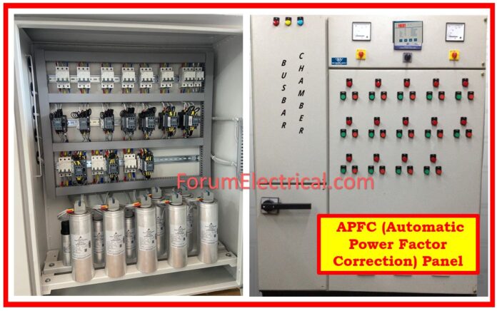
Automatic Power Factor Control, or APFC Panels, are primarily used to increase the power factor.
- What is an Automatic Power Factor Correction Panel?
- APFC Panel Working
- How is APFC panel capacitance calculated?
- Advantages of APFC Panel
- Disadvantages of APFC Panel
- Application of APFC Panel
- Maintenance of APFC Panel
- No Power Factor Improvement
- Three-Phase Capacitor Reading
- Troubleshooting of APFC Panel
- 1). Turn ON Problem
- 2). Capacitor Turn ON Problem
- 3). Connection Overheat
- 4). APFC Panel Overheat
- 5). Low-Current Capacitor
- 6). No Power Factor Improvement
- 7). Fuse Blown (Even Capacitor Healthy)
- 8). Capacitor Leakage
Power Factor is the ratio of the active power to the apparent power, and it is an important factor in calculating electricity consumption.
It is an automatic power factor control panel, which corrects the power factor by switching on/off the necessary units of capacitor banks.

APFC Panel Working
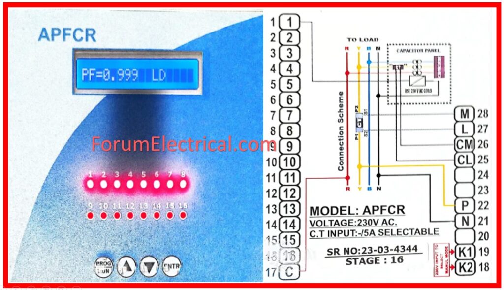
Going by the VAR sensing principle, an APFC Panel with stage based pre-programmed microcontrollers of different brands and which automatically switch on the required capacity of capacitor banks in the multiple stages by directly sensing the kVA reactive load tends to maintain a PF of 0.99 Lag.
As a result, the capacitor banks are selected in stages of 4/6/8 depending on the load pattern which is determined by the customer.
APFC Panels are well-suited for achieving PF of 0.99 Lag.
For this reason the implementation of these control panels turns into necessary in companies where electrical facilities are designed to handle a considerable electrical load.
A decline in power factor can cause operational electric energy losses & may result in a penalty from the electricity distribution networks.
- The circuit receives power.
- The integrated circuit for the microcontroller has a power factor setting that is standard.
- In the case of a deviation, the microcontroller triggers the relay.
- The relay senses & connects the capacitor.
- The capacitor is linked parallel to the load via relay.
- The APFC unit regulates Power Factor (PF) by switching the capacitors ‘ON’ and ‘OFF’.
How is APFC panel capacitance calculated?
Calculate the necessary capacitor:
Ex: Suppose the actual P.F is 0.8, the required P.F is 0.98, and the total load is 516KVA.
Power factor = Kwh/KVAh
KW = kVA x Power Factor
KW = 516 x 0.8 = 412.8 kW
To calculate the required capacitor, multiply kW by the multiplying factor, Required Capacitor = kW x Multiplying Factor
= (0.8 x 516) x Multiplying Factor.

Advantages of APFC Panel
- One of the advantages is a decrease in the requirement for KVA.
- Reduce the current flowing via the line.
- Avoid incurring penalties for power factor.
- A reduction in the rating of the transformer while simultaneously reducing the line loss.
- The reduction in the size of the cable or bus bar.
Disadvantages of APFC Panel
- They only have a limited lifespan of service.
- However, once the capacitor has been destroyed, it is not cost-effective to repair it.
- Static capacitor bank units are less expensive than APFC units, which are more expensive.
- The capacitive loads will not be able to be handled by this equipment.
Application of APFC Panel
- The purpose of this is to enhance the power factor of the inductive loads, such as induction motors.
- When it comes to a transmission system, it is generally considered ideal to have a high power factor in order to decrease transmission losses and enhance voltage.
- In addition to being able to be utilized in substations, it also provides effective voltage regulation.
Maintenance of APFC Panel
The APFC unit requires substantial maintenance checks during “out of maximum demand hours”.
- Switch OFF the system after internal and external tests, for example, late at night or on weekends.
- Remove contactor tops and inspect for wear and capacitance.
- Check and adjust all connections to contactors, capacitors, fuses, etc.
- Re-energize system and measure current (real RMS) & harmonics drawn by each capacitor step.
- Check the voltage level and fuses.
- Tighten any loose connections at the termination.
- Check capacitor current & cable connection.
No Power Factor Improvement
- Check if capacitors with the required KVAr are installed.
- All capacitors should be in APFC mode depending on the load operation.
- Verify CT connection: S1 of incoming bus bar C.T. is connected to S1 of capacitor bank C.T.
- Check if the system’s load demand has increased.
- Ensure the fitted capacitors are appropriate for the purpose and not de-rated.
Three-Phase Capacitor Reading
| KVAr | Line Current @ 440V | Line Current @ 415V |
| 5 | 6.18 | 7.00 |
| 10 | 12.21 | 13.81 |
| 12.5 | 15.50 | 17.33 |
| 25 | 30.88 | 34.92 |
| 50 | 61.78 | 69.70 |
| 75 | 92.80 | 104.30 |
| 100 | 123.77 | 139.12 |
Troubleshooting of APFC Panel
1). Turn ON Problem
Sign:
- The unit doesn’t turn on.
Cause:
- Input auxiliary supply is not working.
- The input side fuses blown out.
Solution:
- Verify the input supply.
- Ensure the unit’s fuses are functioning properly.
2). Capacitor Turn ON Problem
Sign:
- Even when the power factor falls below the lower pf limit, the unit doesn’t turn on any capacitors.
Cause:
- If an auto sync failure notification appears upon powering on.
- The load (KW) is too low.
- Control connections from the RLY module to the contactor coils are incorrect.
Solution:
- Manual synchronization is necessary due to large load fluctuations.
- This is the expected condition.
- Verify control supply & connections from the RLY to the contactor.
3). Connection Overheat
Sign:
- Capacitor terminal gets overheated.
Cause:
- The proper lug size is not used.
- The connection is loose.
- Cable ratings are inadequate.
- The lugs have poor crimping.
- Capacitor draws excess current.
Solution:
- Replace the lug with an appropriate size.
- Tighten loose connections.
- Check the cable’s current carrying capacity & adjust if necessary.
- Ensure proper crimping.
- Check the voltage & lower if necessary.
- Check for harmonics in supply voltage.
4). APFC Panel Overheat
Sign:
- Overheating of the unit.
Cause:
- Poor ventilation.
- Drawing too much current.
- Over voltage.
Solution:
- Ensure cross ventilation in the installation area and panel.
- Check for harmonic presence in network.
- Maintain voltage within limits (according to capacitor specifications).
5). Low-Current Capacitor
Sign:
- Capacitor draws less current.
Cause:
- Low voltage.
- Failure of the capacitor elements.
- Inadequate rating of the short circuit device.
- Harmonic causing.
Solution:
- Ensure voltage is maintained.
- Check that the capacitor is installed and operated according to the guidelines provided.
- An incorrect HRC fuse rating can cause the capacitor element to fail during an overcurrent condition.
6). No Power Factor Improvement
Sign:
- There is no improvement in power factor.
Cause:
- The installed capacitor is not functioning properly.
- Capacitor is always ON.
- Transformers fix compensation is unproven.
- Capacitor installed falls short of requirements.
Solution:
- Verify capacitor operation.
- Allow capacitor to activate just when needed.
- Provide a fixed compensation for the transformer.
- Verify the capacitor rating for adequate installation.
7). Fuse Blown (Even Capacitor Healthy)
Sign:
- The capacitor is in good condition, but the fuse is blowing.
Cause:
- Fuse rating incorrect.
- Harmonic overloading.
Solution:
- Select an appropriate fuse rating.
- Check for harmonic overload & install de-tuned filter banks if needed.
8). Capacitor Leakage
Sign:
- Leakage from the capacitor
Cause:
- The fuse rating is incorrect.
- The overloading of the harmonic.
- The voltage is too high.
- There is no provision for a switching timer (on the delay timer).
- An average temperature that is high.
Solution:
- The said fuse rating has to be selected in an appropriate way..
- Ensure that there is no harmonic overloading, and if necessary, install filter banks that have been detuned.
- In the case that the capacitor does not have any additional issues, replace it.


