
- What is Power Factor?
- Power Factor Unit
- Calculation of the power factor
- Single phase circuit calculation
- Three phase circuit calculation
- Power Factor Values (Resistive, Inductive & Capacitive)
- The importance of the power factor
- Factors affecting Power Factor
- Effects of the Low Power Factor
- The power factor correction
- How power factor can be improved?
- Types of Power Factor
- Why do employ a power factor of 0.8?
- Why is there no power factor in DC?
What is Power Factor?
Power factor is a measure of the efficiency of an electrical system or device in converting electric power into useful work. Power factor is defined as the ratio of the real power (measured in watts) to the apparent power (measured in volt-amperes) in an electrical circuit. Power factor is typically expressed as a number between 0 and 1, or as a percentage.
Real power (kW) is the power that is used to perform useful work in an electrical circuit, such as operating a motor or illuminating a light bulb. It is the product of the voltage across the circuit and the current flowing through the circuit, and is measured in watts.
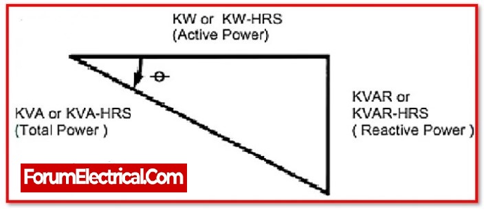
Apparent power (kVA) is the total power that is supplied to an electrical circuit, including both the real power used to perform work and the reactive power used to maintain the electrical fields in the circuit. It is measured in volt-amperes. Reactive power is the power that is used to maintain the electrical fields in capacitors and inductors in an electrical circuit, and does not perform any useful work.
Reactive Power (kVAr) is the amount of power required by some equipment such as transformers and motors to generate a magnetic field that allows real work to be done. This equipment must be powered on, although it does not conduct any condition.
The power factor of an electrical system or device is a measure of how efficiently it uses the electrical power supplied to it. A system or device with a high power factor is more efficient, because it uses a larger proportion of the electrical power supplied to it to perform useful work. A system or device with a low power factor is less efficient, because it uses a smaller proportion of the electrical power supplied to it to perform useful work.
Power factor is an important consideration in electrical engineering and power systems, because it affects the amount of current that is required to deliver a given amount of power, and can impact the design and operation of electrical systems. Improving the power factor of an electrical system or device can have a number of benefits, including reducing energy costs, increasing the lifespan of the system or device, and improving the performance and reliability of the electrical system.
Power Factor Unit
Power factor has no unit because it is the ratio of active to apparent power. Therefore, it is the quantitative measure of how much effective power is being used in the absence of a unit.
Calculation of the power factor
A power quality analyzer or power analyzer that measures both working power (kW) and apparent power (kVA) and calculates the kW/kVA ratio is required to determine power factor.
The power factor formula can be depicted as follows:
Power Factor = True power/Apparent power
OR
PF = W/VA
Where,
W – True or real or actual or active power.
VA – Apparent power.
The ratio of the two is basically active power to apparent power.
The power factor PF for sinusoidal current is equal to the absolute value of the cosine of the apparent power phase angle which is also the impedance phase angle:
PF = |cos φ|= W/VA
The power factor is represented as PF.
φ is the approximate power phase angle.
Single phase circuit calculation
Single phase circuit calculation based on real power meter readings P in kW, V in volts (V), and I in amps (A):
P = |cos φ| = 1000 P / (V x I)
Three phase circuit calculation
Real power meter reading P in kW, line to line voltage VL-L in volts (V), and current I in amps (A) are used to calculate a three-phase circuit:
PF = |cos φ| = 1000 x P / (3 VL-L x I)
Apparent power calculation:
kVA = √3 × VL-L × I / 1000
Reactive power calculation:
kVAR = √ (kVA2 – kW2)
Real power meter reading P in kW, line to line neutral VL-N in volts (V), and current I in amps (A) are used to calculate a three-phase circuit:
PF = |cos φ| = 1000 x P / (3 x VL-N x I)
Apparent power calculation:
kVA = 3 × VL-N × I / 1000
Reactive power calculation:
Q(kVAR) = √ (kVA2 – kW2)
Power Factor Values (Resistive, Inductive & Capacitive)
- Due to the absence of reactive power in the purely resistive circuit, its power factor is 1. In this condition, the power triangle would appear as a horizontal line, since the reactive power side has zero length.
- The power factor for the purely inductive circuit is zero since the true power is zero. In this instance, the power triangle would appear as a vertical line because the actual power side has zero length.
- Equally applicable to a purely capacitive circuit. If there are no resistive components in the circuit, then the actual power must be 0, and any power in the circuit must be reactive.
Similarly, a purely capacitive circuit’s power triangle would be vertical i.e., pointing down instead of up as it was for the purely inductive circuit.
The importance of the power factor
Power factor can be an important element of an AC circuit since a power factor less than 1 requires the circuit’s wire to carry more current than would be required with zero reactance in order to supply the same amount of (active) power to a resistive load.
For Consumers
The consumer pays the bill based on two factors: maximum demand in kVA and the units used. When the power factor is low, the maximum demand for power (kVA) increases, resulting in a higher cost. As a result, Power Factor correction is performed to reduce overall bill amount and annual savings.
For Power Plants or Generating Stations
The rating of generators is done in kVA, but only kW is a relevant output. Because station output equals
kW = kVA x cos φ
Power Factor defines the number of generated units. Power factor should be as high as possible for a high kilowatt hour rating because it reduces the station’s cost and earning capacity.
Factors affecting Power Factor
It is affected by a number of factors, including the load on the system or device, the type of energy conversion process, the quality of the components, and the ambient conditions in which the system or device is operated. Some of the main factors that can affect power factor are:
1). The load on the system or device
The load on a system or device is the amount of work that it is required to perform at any given time. A system or device that is operating at or near its maximum capacity will typically have a lower power factor than one that is operating at a lower load.
2). The type of energy conversion process
Different types of energy conversion processes have different levels of efficiency, and this can affect the power factor. For example, electrical motors are typically more efficient than internal combustion engines, and solar panels are typically more efficient than coal-fired power plants.
3). The quality of the components
The quality of the components used in a system or device can have a significant impact on its power factor. For example, using high-quality electrical components, such as low-resistance wire and high-efficiency motors, can increase the power factor of a system.
4). The ambient conditions
The ambient conditions in which a system or device is operated can also affect its power factor. For example, a system or device that is operating in high temperatures may have a lower power factor than one that is operating in cooler conditions.
5). Inductive Load
A large amount of the power used in industry arrives from inductive loads. The reactive power (KVAR) that the inductive load needs add to the amount of apparent power (KVA) in the distribution system. As the reactive and perceived levels of power increases, the angle gets wider and the cosine, or power factor, increases.
Effects of the Low Power Factor
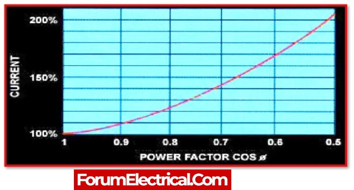
1). Increase Load Current
For a given power and voltage, the current flowing across a line is inversely proportional to the power factor. As a result, a poor power factor will lead to an increased load current and result increased losses.
2). High Copper Loss
Line current is high when the power factor is low. The copper losses are exactly proportional to the line current. As a result, a low power factor leads to more copper losses.
3). High kVA Rating
Transformers and other machines are rated in kVA. kVA is inversely proportional to power factor. A high kVA rating increases cost of the device.
The power factor correction
Power factor correction is a technique that is used to improve the power factor of an electrical system or device. It involves adding capacitors or inductors to the electrical circuit to compensate for the reactive power consumed by the system or device.
When the power factor is near to 1, the reactive power in the circuit is reduced and the majority of the power in the circuit is actual power. This will also reduce power line losses.
Power factor correction capacitor’s capacitance calculation (line to line voltage VL-L):
Qc = Q – Qcorrected (all in kVAR)
C = 1000 × Qc / (2πf×VL-L2)
Power factor correction capacitor’s capacitance calculation (line to line neutral VL-N):
Qc = Q- Qcorrected (All in kVAR)
C= 1000 × Qc / (3×2πf×VL-N2)
Improving the power factor of an electrical system or device can have a number of benefits, including
- Reducing energy costs,
- Increasing the lifespan of the system or device,
- Improving the performance and
- Reliability of the electrical system.
How power factor can be improved?
here are several steps that can be taken to improve the power factor of an electrical system:
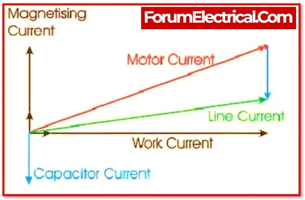
1). Install power factor correction capacitors (Capacitor Bank)
These capacitors can be installed on the load side of the distribution system to correct the power factor by providing a leading current.
The capacitor is the most efficient and economical way to fix the power factor. It makes the power factor better because the effects of capacitance are the exact opposite of those of inductance.
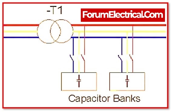
Within the electrical system, capacitors can be placed in to improve the power factor between the point of consumption and the power source. The power factor between the load and the capacitor, on the other side, will remain the same. Capacitors are added to each piece of faulty equipment, groups of motors, motor control centers, distribution panels, and main services.
2). Use power factor correcting transformers
These transformers can be used to correct the power factor by providing a leading voltage.
3). Use power electronic devices
Devices such as static var compensators (SVCs) and thyristor-controlled reactors (TCRs) can be used to dynamically control the power factor.
4). Optimize the load
The power factor can be improved by reducing the level of inductive loads (such as motors) and increasing the level of resistive loads (such as heating elements).
5). Use energy-efficient equipment
Energy-efficient equipment typically has a higher power factor, so replacing older, less efficient equipment with newer, more efficient equipment can improve the power factor of the system.
Types of Power Factor
The power factor of a circuit can be
- Leading,
- Lagging, or
- Unity,
depending on the type of circuit.
1). Leading Power Factor
A leading power factor is seen when the current in a circuit leads the voltage. This occurs in the purely capacitive circuits. In leading power factor, the phase angle between the current and voltage is positive. The value of the leading power factor is from -1 to 0.
2). Lagging Power Factor
When the current in a circuit is lag behind the voltage, the power factor is called lagging power factor. This occurs in a pure inductive circuit. In this circumstance, the phase angle between the current and the voltage is negative. The value of lagging power factor ranges from 0 to 1.
3). Unity Power Factor
When the current and voltage are in phase, the power factor is 1. A power factor of 1 only occurs in ideal circuits. A circuit with a power factor of 1 uses no reactive power. The value always is one.
Why do employ a power factor of 0.8?
A common industry standard generator power factor rating is 0.8, or 80%, which means that these loads can utilize 80% of the generator’s power supply. Power Factor or PF for generators with a power factor rating of 0.8 are almost always three-phase generators.
Why is there no power factor in DC?
Since direct current is accompanied by zero frequency, it has no power factor. Power factor is a norm for alternating current voltages and runs between zero and one, with one being the ideal system and 0 being the poor system.