What is a Capacitor Bank?
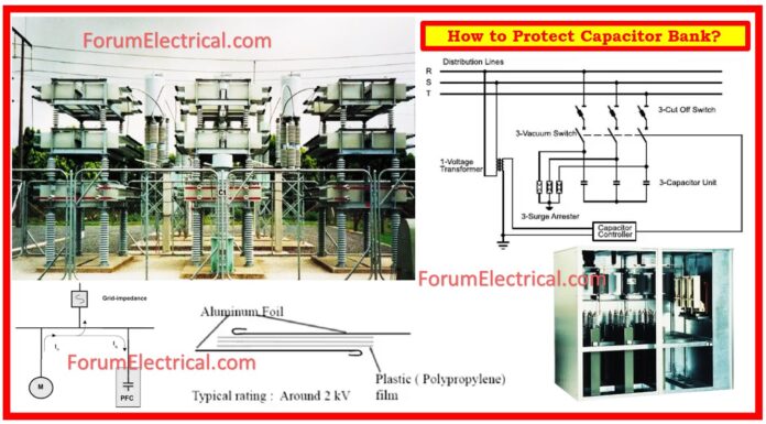
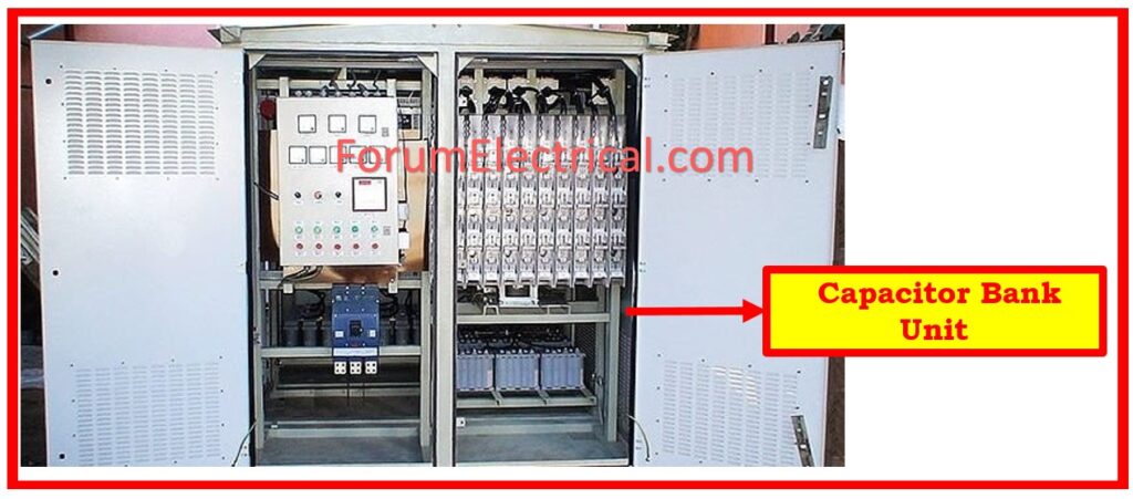
A capacitor bank stores energy by connecting capacitors in series or parallel. This method corrects AC power factor lag & phase shift, improving electrical energy transfer efficiency.
- What is a Capacitor Bank?
- Protection of Capacitor Bank
- Capacitor Bank Fault Types
- 1).Overload
- 2). Short Circuit
- 3). Frame Fault
- 4). Short Circuit Capacitor Component
- Capacitor Bank Protection
- 1). Element Fuses
- 2). Unit Fuse
- 3). Overload Protection
- 4). Short Circuits Protection
- 5). Frame Fault Protection
- 6). Short Circuit Capacitor Component Protection
- Capacitor Calculator
Modern life requires electrical power systems, which must be regulated. Capacitors banks can regulate the system.
Capacitor banks store electrical energy and use it to correct power factor lags (or) phase shifts in AC power systems. This maximizes efficiency and eliminates voltage drops and surges that damage electrical equipment.
Protection of Capacitor Bank
Several methods are utilized for protecting capacitor banks.
These methods include avoiding re-energizing them unless they have been discharged, implementing a time delay prior to re-energizing in order to avoid transient overvoltage, & making use of quick discharging reactors in order to reduce the amount of time required for discharge.
Protective controls are also extremely important because they should be able to cut off service to the bank in the event that any of the units exceed 110% of their intended voltage rating.
Monitoring for imbalances is also important since it may indicate faults like as
- Blown fuses (or)
- Short circuits,
which are both potential problems.
The reactive energy that is spent by loads in an electrical system can be compensated for by capacitor banks, which may also form filters to reduce the negative effects of harmonic voltage.
They have a purpose of improving the overall quality of the electrical system.
Depending on voltage level & the requirements of the system, they can be organized in
- Star Configuration,
- Delta Configuration, (or)
- Double-Star Configuration.
Insulating terminals are often located near the top of a capacitor, which is that it is typically enclosed.
It is made up of individual capacitors that have maximum voltages that are defined (for instance, 2250 V), and these capacitors are connected in series to obtain the required voltage tolerance, and in parallel to get the power rating that is required.
Capacitor Bank Fault Types
Electrical systems need capacitor banks for power quality and efficiency. Here are some types of faults that can affect these banks:
- Overload,
- Short Circuit,
- Frame-fault
- Short Circuit Capacitor Component.
1).Overload
Fault: A sudden overcurrent that is connected to the process of powering a capacitor bank step will occur. When overloads are present, they cause the capacitor to overheat, which has a negative impact on the dielectric withstand and causes the capacitor to age prematurely.
Protection Consideration: An key component for correcting reactive energy in the electrical systems & enhancing the overall quality of the system is the utilization of overload capacitor banks.
The following are the most important aspects concerning overload protection:
An overload happens when the capacitor bank is subjected to an overcurrent that is either there temporarily or there continuously.
The following are some of the possible causes of constant overcurrent:
- Variations in voltage of power supply are commonly referred to as voltage fluctuations.
- The generation of harmonic currents occurs when non-linear loads, such as rectifiers, variable speed motors, and arc furnaces, are present.
- During the process of powering a capacitor bank step, there is a momentary phenomenon of overcurrent.
- The overheating that occurs as a result of overloads has a negative impact on the dielectric withstand and speeds up the aging process of capacitors.
2). Short Circuit
Fault: A short-circuit is an electrical problem that can occur either internally or externally between live conductors.
It can occur
- Phase-to-Phase (or)
- Phase-to-Neutral,
relying on the connection of the capacitors, which can be either delta or star.
The presence of gas within the protected chamber of capacitor has the potential to generate an excessive amount of pressure, which could result in the casing opening and the dielectric leaking.
It is possible for a short circuit to occur between live conductors as a result of an internal (or) external fault.
It is dependent on whether the capacitors are connected in a
- Delta-Connected or
- Star-Connected Connection
as to the type of the problem.
After a short circuit has occurred, there is a possibility that the gas-tight chamber of capacitor will experience an increase in pressure.
This excessive pressure has the potential to force the case to open, which could result in the presence of dielectric material leaking out.
Protection Consideration: The following precautions should be taken into consideration in order to safeguard capacitor banks against earth faults and short circuits:
- Asymmetry that is caused by blown internal fuses, short circuits across the bushings, (or) defects between capacitor units & their mounting racks might be detected by an unbalance relay. Every capacitor unit is composed of a number of different components that are protected by the internal fuses.
- Protecting against earth faults and short circuits requires the utilization of two (or) three-phase short circuit protection in conjunction with an earth overcurrent relay. This type of protection is known as ordinary short circuit protection.
3). Frame Fault
Fault: When there is an internal fault across a live component of a capacitor & the frame that is formed by its metal enclosure, this type of failure is referred to as an A-frame fault.
Because of this fault, which is comparable to internal short circuits, there is a possibility that the capacitor may experience an accumulation of gas within its sealed chamber, which would finally lead to an extreme pressure.
Due to the excessive pressure, the casing may become open, which would result in the dielectric leaking.
It is within the gas-tight chamber of capacitor that a frame fault becomes apparent.
The development of gas (as a result of a fault) results in overpressure, which is analogous to the phenomenon of internal short circuits.
As a result of this excessive pressure, the case can become open, which would result in the dielectric substance leaking out.
Protection Consideration: For the capacitor bank to continue to be reliable, it is essential to identify and correct any frame errors that may occur.
- Any faults, whether they are internal (or) external to capacitor bank, must be covered by the appropriate protection methods.
- When particular types of fuses are employed, such as internally fused (or) fuse less banks, the process of identifying problematic capacitor units becomes more complicated.
- This presents difficulties for both maintenance and fault investigation.
4). Short Circuit Capacitor Component
Fault: The malfunctioning unit is responsible for shunting the parallel-wired individual capacitances because it does not have any internal protection:
Impedance of the capacitor is altered in this way.
Within the series, the voltage that is supplied is spread to one group less than before.
Every group is subjected to a higher level of stress, which may lead to more flashovers that cascade into one another, all the way up to a complete short circuit.
Indications of a short circuit in capacitor is the absence of resistance, which is sometimes referred to as impedance, across the 2 terminals of the capacitor.
Several factors may contribute to this condition:
- In the case that there is a direct wire link among the terminals of a component, the component is referred to as being short-circuited or shorted.
- Because this wire goes around the capacitor, the capacitor is rendered ineffective within the circuit.
- Voltage across the capacitor that has been shorted.
Capacitor Bank Protection
1). Element Fuses
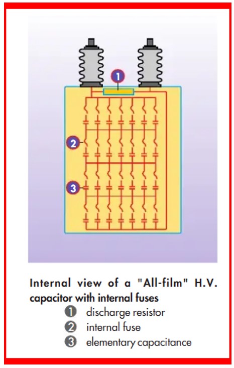
Typically, manufacturers incorporate fuses into every capacitor element.
An element that malfunctions is instantly cut off from the remainder of the unit. The equipment can still operate, but its output will be lower.
Only these integrated protection systems are utilized for smaller capacitor banks in order to save money on external protective equipment.
2). Unit Fuse
The duration of the arc in defective capacitor units is limited by unit fuse protection.
This protects nearby units by lowering the possibility of significant mechanical damage & gas production.
If every capacitor bank unit contains its own fuse, then the bank can keep running even if one of the units fails, as long as the malfunctioning unit is taken out and replaced.
The ability to identify the exact position of the malfunctioning unit is another important advantage of fuse protection for every bank unit.
However, the fact that the fuse element has to tolerate excessive loading because of system harmonics should be taken into account when selecting the fuse size for this reason.
Accordingly, the fuse element’s current rating for this use is 65% higher than the full load current. It is important to supply discharge resistance in every capacitor bank unit when each unit is fused for protection.
3). Overload Protection
It is important to keep in consideration that the longevity and dependability of capacitor banks are dependent on the appropriate protection.
Through the management of overloads and other defects, we are able to keep power systems operating efficiently while also protecting essential equipment.
Overvoltage protection keeps monitoring on the voltage in the system, preventing overcurrent that lasts too long due to a spike in the power supply voltage.
While this protection may be capacitor-specific, it is most often used as an integral component of a system-wide plan to prevent damage to the electrical system.
Additional protection might not be necessary because capacitors can usually withstand voltages up to 12 hours per day at 110% of their rated capacity.
This type of overload prevention may detect long-lasting overcurrent that is generated by harmonic current flow. The subsequent types of the overload prevention are accessible:
- Thermal overload
- Time-delayed overcurrent
As long as harmonic frequencies are considered. With each step, series-mounting impulse reactors restrict the amplitude of short-duration over-current caused by the energizing of capacitor banks.
4). Short Circuits Protection
The longevity of capacitor banks and their ability to function dependably are both ensured by the appropriate protection.
By correcting short circuits & other faults, we are able to maximize the effectiveness, dependability, and quality of the infrastructure that supplies electrical power.
Short circuits are detected using a time-delayed overcurrent protection system. Current & time delay setting allow you to operate at the maximum permitted load current when closing and switching steps.
5). Frame Fault Protection
Frame faults pose a threat to the integrity of the capacitor bank.
For the purpose of ensuring safe operation & decreasing the probability of damage, the deployment of adequate protective measures is considered to be of utmost importance.
Protection depends on grounding. Time-delayed earth fault protection is utilized for grounded neutrals.
Short-circuiting a capacitor component causes a change in impedance, which is detected for capacitors without internal protection and by eliminating the faulty capacitance for the capacitors with internal fuses.
The unbalance caused by change in impedance in one star cause’s current to flow between the neutral points in a double-star capacitor bank. A sensitive overcurrent protection device detects this imbalance.
6). Short Circuit Capacitor Component Protection
Due to the presence of internal protection, the removal of the faulty individual capacitance is accomplished by melting the associated internal fuse.
This ensures that the capacitor continues to function with an impedance that has been adjusted appropriately.
To properly analyze circuits and ensure that they are operating correctly, it is necessary to have a solid understanding of short circuits.
Capacitors are essential components in electrical systems, & the way in which they react to malfunctions has a substantial impact on the overall functioning of the system.


