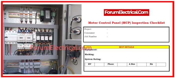
What is a Motor Control Panel?
An electric motor control panel (MCP) distributes power to electric motors throughout an industrial site using a mix of drives, switches, relays, & transformers. These control panels may be utilized for both low and medium voltage applications.
Scope
This Checklist includes important actions to assure the system’s operational efficiency and safety.
Key information such as the consumer’s name and work number are saved for future reference and traceability.
The MCP (Motor Control Panel) details, such as
- Equipment type,
- Marking, and
- System rating (KV, phase, bus, and frequency),
are described to comply with engineering criteria.
Visual Inspection
This entails performing a broad inspection of the panel to identify potential flaws, checking for physical damage such as bent doors or faulty ground bonding, and evaluating the quality of instruments, relay cover glass, & phase indication lights.
The bus is also inspected for exterior damage, missing insulation, & adequate connections at joints.
The cleanliness of cubicles (or) compartments is ensured, & insulation, standoff insulators, & bus separators are checked for damage or clearance problems.
Proper separation is ensured, & the color and painting are examined in accordance with the work standards.
Mechanical Inspection
Mechanical inspections are designed to ensure both the functional and structural integrity of the system.
This comprises inspecting bus bars, joints, torque, and markings, as well as examining bus support, spacing, marking, sizing, & clearance.
The alignment and flexibility of the breaker mechanisms are examined, as well as the condition of the rails, guides, rollers, & shutter mechanisms.
Positive & negative interlocking mechanisms are examined to ensure correct function.
Breakers are manually connected and unplugged, and their compatibility with others of the same rating is validated.
Interface-rejection plates are also tested for correct installation and alignment according to the setup.
Electrical Inspection
The electrical examination ensures the system’s electrical integrity & operational functionality.
Control wiring is examined point-by-point against the drawing design, & terminal block connections are secured and properly identified.
Megger tests are performed on the main bus to assess
- Phase-to-Ground &
- Phase-to-Phase insulation resistance.
Hi-pot testing lasts one minute between phases & ground at the rated voltage.
- Voltmeters,
- Ammeters, &
- Protection Relays
are tested for functionality, with relays turned on and configured to factory settings, and trip/alarm functions checked.
The functionality of power circuit breaker systems is certified, & control circuit performance is verified against engineering drawings.
Final Inspection
The final inspection verifies that the system satisfies all standards and is ready to operate.
- Nameplates for master,
- Warning,
- Data, &
- Component labels
have been confirmed.
All essential protective barriers are examined before installation.
The paint finish is checked for color accuracy and defects, & the setup for short shipment is validated if necessary.
Hardware, straps, & installation components are evaluated.
The switchgear assembly is checked against engineering-issued drawings to ensure its suitability for labeling.
Certification and Remarks
The system is tested and inspected by qualified personnel, with notes made for future reference.
The testing and inspection are recorded to guarantee compliance with engineering and safety standards.
This thorough procedure ensures the system’s reliability and safety prior to commissioning.


