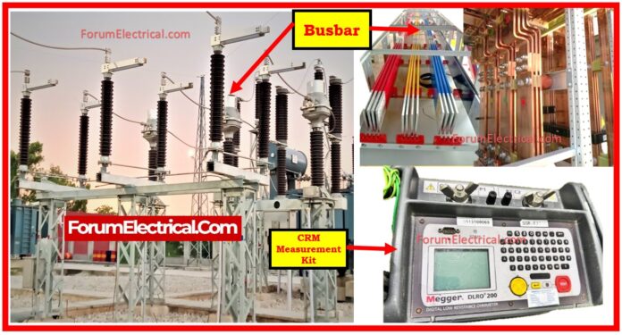
What is Contact Resistance?
Contact resistance is the resistance to the current flow caused by surface conditions and other factors when contacts come into contact (in the device’s closed state). This can happen between contacts like:
- Circuit breakers and contactors
- Relays, switches, and connectors
- Other switching devices
Contact resistance testing, also known as Ductor testing, determines the resistance of the electrical contacts.
132 kV Busbar Contact Resistance Testing
Busbars are essential components in high-voltage substations for safely and efficiently delivering electrical power.
To make sure optimal performance and prevent unnecessary power losses (or) equipment failures, the reliability of busbar connections must be tested on-site.
The Busbar Contact Resistance Test is an important testing procedure, especially for systems operating at 132 kV.
This test confirms that all busbar joints & connections have minimal contact resistance, which is essential for reducing heat generation & energy loss.
In addition, insulation resistance tests are performed to ensure electrical isolation across phases & ground.
This post explains the site test process for testing 132 kV busbars for contact resistance and insulation resistance in accordance with the approved Site Inspection & Test Plan (ITP).
It goes over responsibilities, purpose, necessary equipment, test processes, & acceptance criteria in detail.
Responsibility
The Commissioning Manager is ultimately responsible for the design and accuracy of this instructions.
The Commissioning Engineer is liable for carrying out the test procedure on-site in accordance with the recommendations provided.
Purpose
The primary purpose of the busbar contact resistance test is to:
To reduce resistive losses and prevent localized heating, ensure that the electrical contact resistance of busbar joints is as low as possible while remaining within prescribed standards.
Check the electrical continuity & mechanical tightness of all busbar joints & connections.
Check that the busbar system is fitted in line with design & manufacturer specifications to ensure the substation’s reliable functioning.
Safety Precautions
- De-energize, isolate, and ground all busbars before testing.
- Protect yourself and follow lockout/tagout procedures.
- Only qualified people can calibrate and operate test equipment.
Equipment Required
The contact & insulation resistance tests require the following calibrated test instruments:
- Micro Ohm Meter (MOM) – Capable of injecting high DC currents (usually 100 A or greater).
- The CPC 100 or equivalent test system – Utilized for accurate resistance measurement & insulation testing.
- 5 kV Insulation Resistance Tester – Used to evaluate insulation resistance values across phases & ground.
Reference
- The busbar system instructions manual & technical datasheet are provided by the manufacturer.
- Contact resistance values are reported in Factory Acceptance Tests (FATs).
- The site inspection & test plan (ITP) has been approved for the work.
Methods of Inspection
General Data & Information
- Conduct a visual inspection of a complete busbar assembly.
- Check the busbar rating (voltage, current, short-circuit withstand) against the design documentation and nameplates.
- Look for apparent signs of physical damage, corrosion, incorrect alignment, or loose fittings.
Electrical Tests
Before starting, make sure that:
The test format or template is created and delivered to the client (or) third-party witness for inspection and approval.
All test checklists are printed out and evaluated by the testing team.
FAT contact resistance results are provided on-site for comparison.
Contact Resistance Test Procedure
Path Selection
Specify and mark the start and finish points of each busbar segment (or) joint that will be tested.
Current Injection
Utilizing a Micro Ohm Meter (or) CPC 100, inject at least 100 A of DC current along the defined channel.
Voltage Drop Measurements
Use precision probes to measure the voltage drop (in millivolts) around the test area.
Resistance Calculation
Calculate the resistance utilizing Ohm’s Law:
R = V/I
where
R – Resistance (Ohm),
V – voltage drop (V), &
I = Test Current (A).
Record Readings
Document all readings on the test sheet, and carefully identify each test point.
Comparison to Factory Data
- Compare the measured resistance levels to those obtained during the factory test.
- Check that the deviation does not exceed the permitted limit (often in the micro-ohm range, such as < 150 µΩ per joint).
Insulation Resistance (IR) Test Procedure
Test Voltage
Using a 5 kV insulation tester, analyze the insulation resistance of the following combinations:
- R-Earth (G)
- Y-Earth (G)
- B-Earth (G)
- R – Y
- R – B
- Y – B
Measurement
Observe and note the insulating resistance values for every combination.
The normal approval standards for 132 kV systems require each reading to exceed 100 MΩ.
Acceptance Standards
| Test | Acceptance Value |
| Contact Resistance | Within factory-specified limits (usually < 150 µΩ). |
| Insulation Resistance | Minimum 100 MΩ between all phase-ground combinations. |
Summary
Busbar Contact Resistance & Insulation Resistance Tests are essential for 132 kV substation commissioning.
Busbar installations are tested for electrical and mechanical quality, dependability, safety, and design and manufacturer conformity.
Engineers can identify overheating and failures caused by faulty connections, loose joints, (or) surface oxidation by measuring and analyzing contact resistance.
Insulation resistance tests verify dielectric strength and phase separation for safe operation.
Applying a well-defined test plan & comparing on-site results with factory data helps identify possible faults early, decreasing downtime and extending equipment life.


