
What is a Bus Coupler?
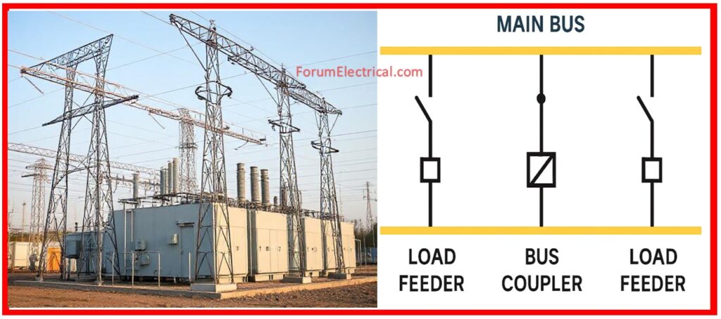
Bus Couplers are switching devices, which are often circuit breakers, that are utilized to connect two (or) more busbars that are located within a substation.
- What is a Bus Coupler?
- Why do Substations use Bus Couplers?
- Functions of a Bus Coupler
- Where do Bus Couplers fit in Busbar Schemes?
- Main & Transfer Bus Scheme
- Double Bus, Single Breaker Scheme
- Double Bus, Double Breaker Scheme
- Working Principle of Bus Coupler: Step-by-Step Procedure
- Step 1: Normal Operations
- Step 2: Maintenance Condition
- Step 3: Restoration
- Advantages of Bus Couplers
- Applications of Bus Couplers
- Summary
Unlike feeders (or) incoming lines, the Bus Coupler does not supply (or) receive electricity directly from the grid or load.
Rather, it is coupled to the load.
On the other end, it functions as a bridge, making it possible to accomplish regulated connections and disconnection of various bus sections in accordance with the requirements of the operation.
Ex: Consider of it as a flexible connection in a railway system – not transporting people itself, but allowing trains (in this circumstance, power) to move between tracks (busbars) effortlessly and safely.
Why do Substations use Bus Couplers?
- Reliability,
- Redundancy and
- Maintainability
are essential features of modern power systems.
A single point of failure (or) an inflexible arrangement may result in extended outages or risky repair procedures. That’s the reason when the Bus Coupler becomes important.
Functions of a Bus Coupler
- During maintenance or faults, the load is seamlessly transferred from one busbar to another.
- Reduce the impact of a fault to a specific section, preventing a system-wide disruptions.
- Isolate breakers (or) busbars without disrupting continuous supply.
- Increase operational flexibility by dynamically reconfiguring bus schemes depending on load demand (or) contingency requirements.
Where do Bus Couplers fit in Busbar Schemes?
Substations use different busbar layouts depending on voltage levels, load profiles, & criticality.
Bus Couplers are fundamental in several common configurations:
Main & Transfer Bus Scheme
- Feeders are connected to the primary bus by separate breakers.
- Normally open, only utilized for maintenance or emergencies.
- Cost-effective design with considerable flexibility.
Double Bus, Single Breaker Scheme
- Isolators allow each feeder to alternate between buses A and B.
- A Bus coupler breaker joins both buses as necessary.
- Ideal for systems that require redundancy & load balancing.
Double Bus, Double Breaker Scheme
- Every feeder has 2 breakers: one for each bus.
- The bus coupler facilitates bus connections.
- Preferred for essential substations (Ex: industrial, metro, airport) with zero tolerance for downtime.
Working Principle of Bus Coupler: Step-by-Step Procedure
Let’s explore how a Bus Coupler works during Main and Transfer Bus Scheme operation.
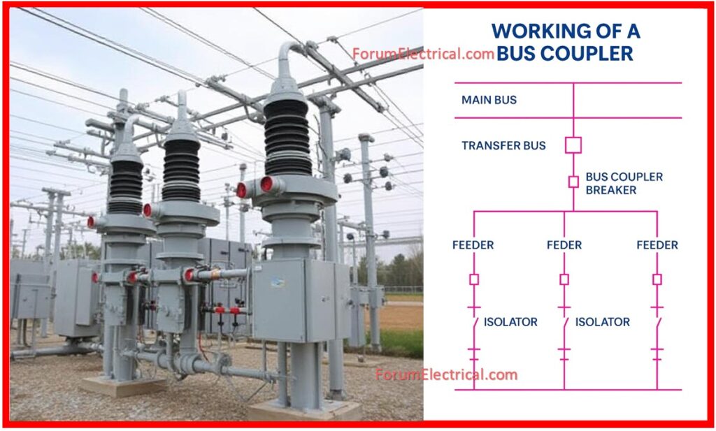
Step 1: Normal Operations
- The load flows via the main bus.
- The Transfer Bus & Bus Coupler remain in standby mode (open).
Step 2: Maintenance Condition
- Assume a feeder breaker on Main Bus requires servicing.
- The feeder is isolated from a Main Bus by isolators.
- The same feeder is currently connected to a Transfer Bus via an isolator.
- The Bus Coupler Breaker is closed, which powers the Transfer Bus from the Main Bus.
- The load continues to flow via the Transfer Bus & Bus Coupler, ensuring no interruptions.
Step 3: Restoration
- Following maintenance, the feeder is connected back to the Main Bus.
- The Bus Coupler is now open again.
- The system returns to its previous state, with no power loss.
- This elegant switching mechanism is the foundation of live maintenance, which is essential for substations that feed electricity to sensitive infrastructures such as hospitals, data centers & manufacturing plants.
Advantages of Bus Couplers
- This function provides an alternative power path in the case of a failure or repair.
- Provides assistance in the process of load transfer and balance between the various buses.
- It makes it possible to do maintenance on the live systems without leaving personnel or equipment in danger.
- During maintenance or repairs, downtime is reduced to a minimum.
- Provides support for future expansion and upgrades without requiring significant design changes.
Applications of Bus Couplers
- In order to guarantee uninterrupted metro (or) hospital operations, urban substations are installed.
- Substations in industrial settings that require a high level of dependability, such as those found in chemical, steel, and cement industries.
- Substations of the grid that are accountable for linking the power flows of interconnected regions.
Summary
The Bus Coupler may be silent when operating, but its effect on the system stability & operational excellence is significant.
By allowing for
- Dynamic reconfiguration,
- Safe maintenance and
- Fault isolation
modern substations are not only functional, but also resilient and future-ready.
When planning or renovating a substation, never overlook the significance of a bus coupler; it might be the difference between a minor failure and a severe outage.