 via electromagnetic induction. Understand its working principle, construction, types, advantages and uses.)

What is an Induction Disc Relay?
An Induction Disc Relay is an electromagnetic safety device that works in the same way as a split-phase induction motor.
- What is an Induction Disc Relay?
- Working Principle of Induction Disc Relay
- Construction of Induction Disc Relay
- How does an Induction Disc Relay Work?
- Types of Induction Disc Relays
- 1). Watt-Hour Meter Type Induction Relay
- 2). Shaded Pole Type Induction Relay
- Advantages of Induction Disc Relays
- Disadvantages of Induction Disc Relays
- Applications of Induction Disc Relays
It employs the interplay of magnetic fluxes to generate a force (torque) that moves a revolving disc, which then works a contact to trip a circuit breaker.
This relay only works in alternating current circuits since it is based on alternating fluxes.
Working Principle of Induction Disc Relay
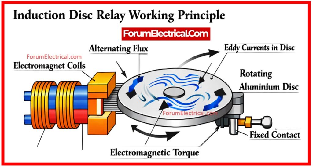
The Induction Disc Relay operates on the fundamental principle of electromagnetic induction.
Alternating Flux
When alternating current (AC) runs through the relay coils it produces alternating magnetic fluxes.
Eddy Currents
These fluxes cut across a metal disk (often aluminum) causing eddy currents within it.
Torque Generation
Torque generation occurs when the magnetic field of eddy currents interacts with the original magnetic field resulting in torque (rotational force).
Rotation
The torque rotates the disc. If the torque is sufficient (due to a large fault current) the disc spins far enough to seal the contacts.
Point to Remember:
It should be noted that generating this torque requires a phase difference across the interacting fluxes.
Construction of Induction Disc Relay
Electromagnets
Typically two which generate the required magnetic fields.
Rotating Disc
An aluminum disc inserted between the electromagnet poles.
Moving Contact
Affixed to the disc’s shaft.
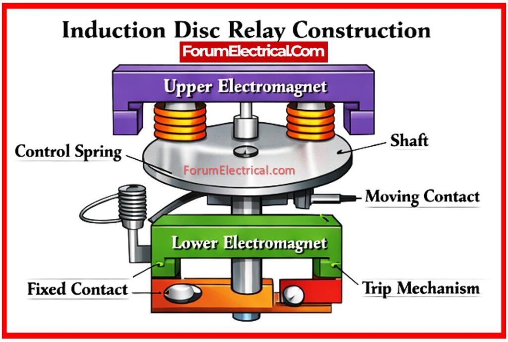
Restraining Spring
Keeps the disk in place during regular operation.
How does an Induction Disc Relay Work?
Normal Condition
The current is low. The restraining spring force is greater than the magnetic torque therefore the disc stays stationary.
Fault Condition
A large fault current runs through the coils activating the electromagnets significantly.
Induction
The strong magnetic field causes large eddy currents in the disk.
Trip
The resulting torque exceeds the spring force. The disc rotates causing the moving contact to touch the fixed contact.
This closes the trip circuit & shuts down the power supply.
Reset
After the error is resolved the spring pushes the disc back to its normal position.
Types of Induction Disc Relays
There are 2 primary types of induction disc relays that are require to generate the needed phase difference for rotation:
1). Watt-Hour Meter Type Induction Relay
2). Shaded Pole Type Induction Relay
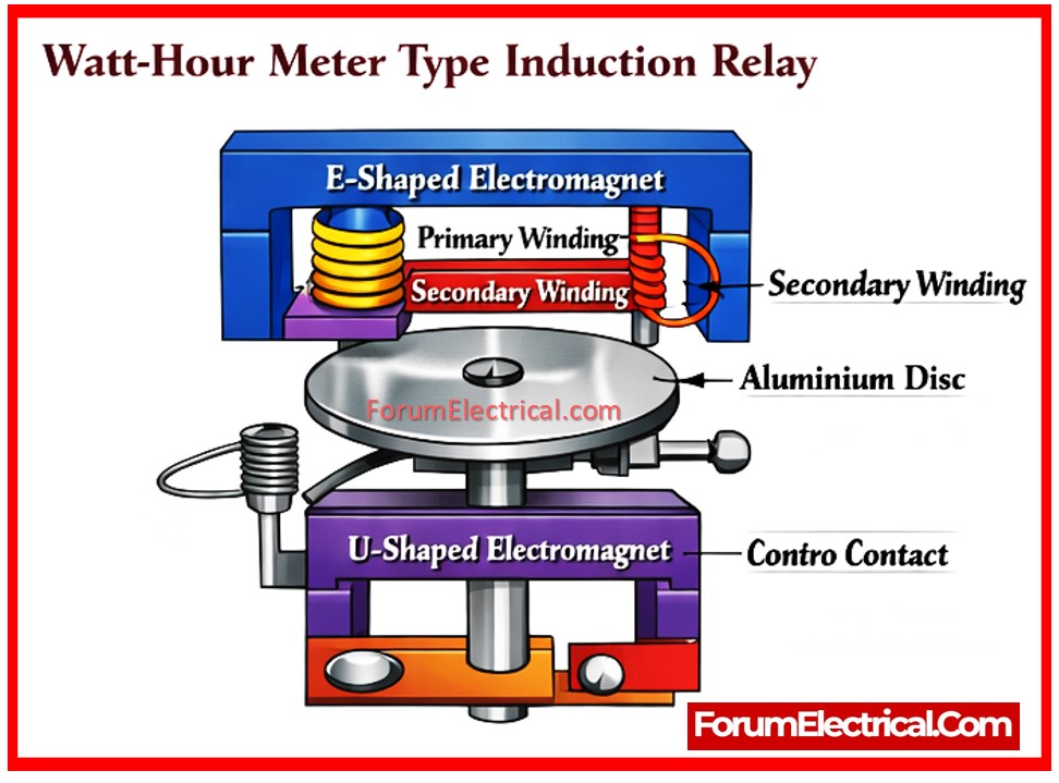
1). Watt-Hour Meter Type Induction Relay
This construction of Watt-Hour Meter Type looks like a normal energy meter.
Its structure consists of an E-shaped upper electromagnet & a U-shaped lower electromagnet.
The upper magnet contains both primary & secondary windings.
Opening the secondary winding circuit prevents torque generation thereby turning off the relay.
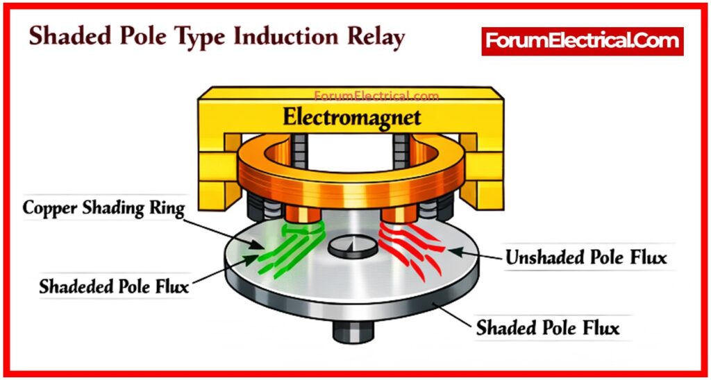
2). Shaded Pole Type Induction Relay
Shaded pole type creates the phase shift using a special pole design.
Copper rings are wrapped around the pole faces.
The flux in “shaded” part (inside the ring) lags beneath the flux in the “unshaded” part by 40-50°.
The phase difference across the two fluxes produces the “shifting” magnetic field required to rotate the disk.
Advantages of Induction Disc Relays
1). Induction disc relays are robust and mechanically resistant construction.
2). Induction disc relays are reliable and accurate performance.
3). Induction disc relays are easy change of current and time settings.
4). Induction disc relays are ideal for overcurrent protection.
5). Induction disc relays are high reset-to-pickup current ratio.
Disadvantages of Induction Disc Relays
1). Induction disc relays are requires periodic testing and maintenance.
2). Induction disc relays are affected by dust, corrosion & aging.
3). Induction disc relays are mechanical inertia limits the operating speed.
4). Induction disc relays are no inherent directional characteristic.
5). Induction disc relays are needs heavy-duty CTs (Current Transformer) and PTs (Potential Transformer).
Applications of Induction Disc Relays
These relays are most suitable for:
1). Conditions requiring substantial dependability and durability.
2). Applications that need low-speed operation or particular time-delay functionality.
3). Protection methods require a high reset-to-pickup ratio.