 Testing Procedure")
- What is a Potential Transformer or Voltage Transformer (PT/VT)?
- Potential Transformer (PT) Testing
- 1). Visual & Mechanical Inspections
- 2). Insulation Resistance (IR) Test
- 3). Polarity Test
- 4). Ratio Test
- 5). PT Secondary Injection Test
- 6). PT Combined Primary & Secondary Injection Test
- 7). Phasing Test
- 8). Winding Resistance Test
- Applicable Standard
- Maintenance
- What is a CT/PT Analyzer?
- Difference between Current Transformer and Potential Transformer
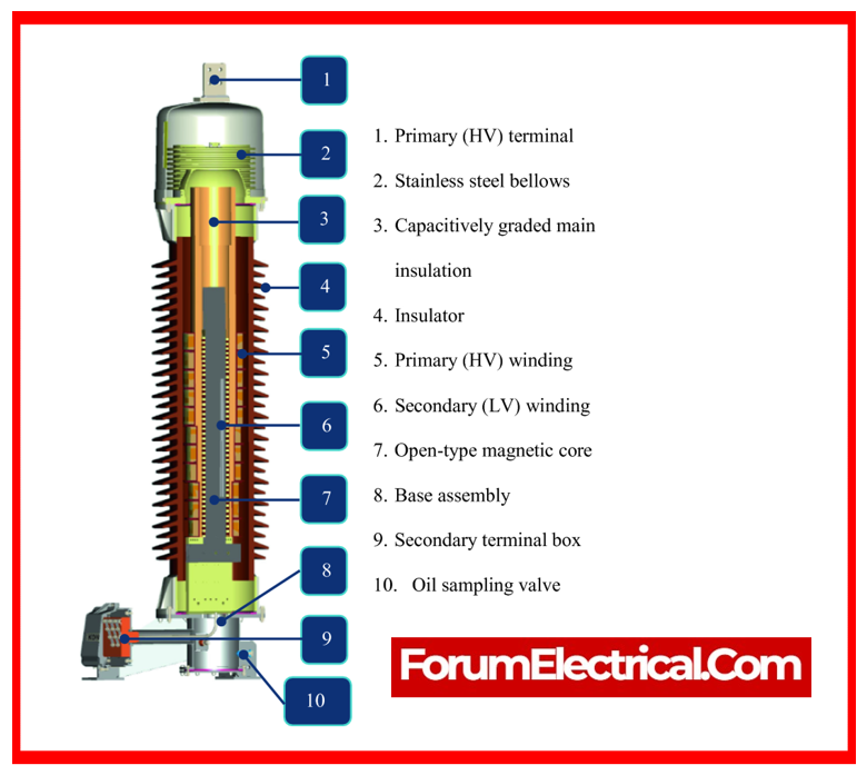
What is a Potential Transformer or Voltage Transformer (PT/VT)?
A potential transformer is utilized to measure and protect equipment in a substation.
A potential transformer uses the electromagnetic induction principle to convert into high voltage to low voltage so that it may be easily read by measuring instruments.
It has a primary winding linked in parallel to the high voltage circuit & a secondary winding connected to the measuring (or) protection instruments.
Potential Transformer (PT) is commonly used in the bus-coupler bay of a substation to measure bus voltage.
Potential Transformer has been developed to present a small load to the supply being measured while maintaining an exact voltage ratio & phase relationship for secondary connected metering.
Potential Transformer (PT) Testing
The importance of the transformer testing is frequently neglected. Testing before initial use can greatly decrease risks such as confounding instrument transformers for metering & protection or mismatching connections.
At the same time, damage to the interior of a potential transformer, such as those generated during transportation, are easily identified.
Changes in an instrument transformer, such as those induced by aged insulation, can also be detected.
As previously stated, PT has multiple cores that serve various functions. Pre-commissioning testing is conducted on several cores and they are
1). Visual & Mechanical Inspections
2). Insulation Resistance (IR) Test
3). Polarity Test
4). Ratio Test
5). PT Secondary Injection Test
6). PT Combined Primary & Secondary Injection Test
7). Phasing Test
8). Winding Resistance Test
1). Visual & Mechanical Inspections
- Compare the equipment (PT) nameplate information with drawings & specifications.
- Inspect the physical and mechanical conditions.
Ensure that all grounding connections make contact. - Check the transformer withdrawal mechanism & grounding operation to ensure they are functioning properly.
- Verify that the primary & secondary fuse sizes are correct.
- Check mechanical alignment of the PT power jaws.
- PT primary winding star earthing.
- Check the PT trolley moves freely.
- Check tightness in all connections
2). Insulation Resistance (IR) Test
To test insulation resistance, use the Megger.
Procedure
- Disconnect the PT secondary circuit wiring.
- Disconnect the PT primary & secondary neutral earthing.
Record IR values for:
- Primary to Earth Insulation Resistance Measurement
- Primary to Secondary Insulation Resistance Measurement
- Secondary to Earth Insulation Resistance Measurement
- Winding to Winding Insulation Resistance Measurement
Reconnect the primary & secondary neutral earthing.
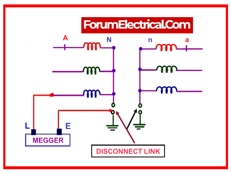
a). Primary to Earth Insulation Resistance (IR) Measurement
- Connect the test setup according to the diagram.
- Note the IR readings at 5kV.
- The minimum permissible value is rated voltage 1 MΩ.
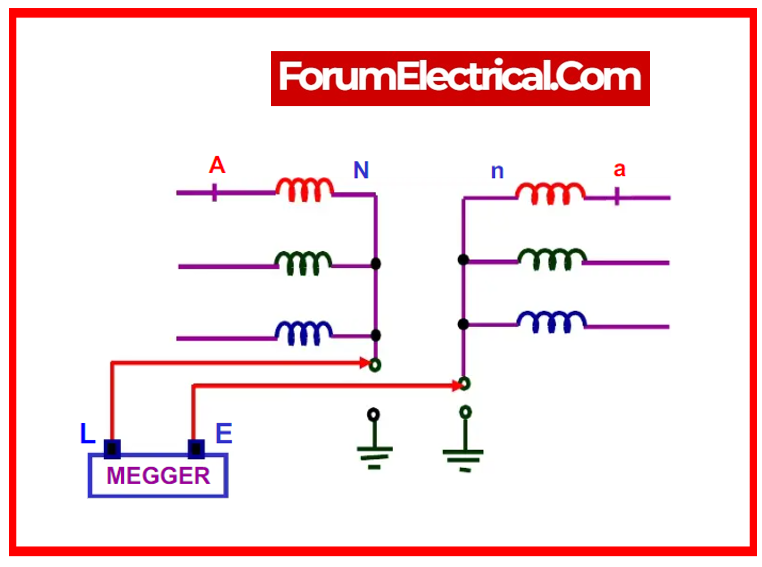
b). Primary to Secondary Insulation Resistance (IR) Measurement
- Set up the test according to the diagram.
- Note the IR readings at 5kV.
- Minimum acceptable value: >1 MΩ.
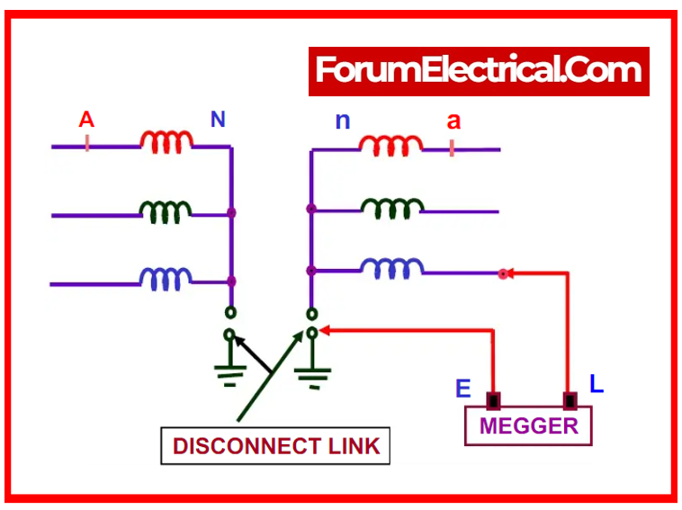
c). Secondary to Earth Insulation Resistance (IR) Measurement
- Set up the test according to the diagram.
- Take note of the IR measurements at 500 volts.
- Minimum acceptable value: > 1 MΩ.
d). Winding to Winding Insulation Resistance (IR) Measurement
- Set up the test as shown in the diagram.
- Take note of the IR readings at 500V.
- The minimum acceptable value is > 1 MΩ.

After the testing are completed, reconnect the PT primary & secondary neutral connections to earth. Measuring the value confirms that it is zero.
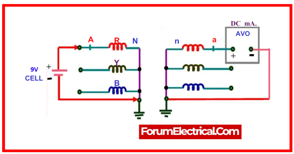
3). Polarity Test
This test is required to determine the relative polarity of the primary & secondary terminals when the terminals are not marked, or to confirm the accuracy of the marking if the terminals are already marked.
This test is performed out with a 9v (or 12v) DC battery.
Apply the DC source between the primary terminals P1 (+) and P2 (-), & measure the secondary side with a null deflection analog ammeter.
Check the accurate deflection of the meter and compare it to the polarity mark.
Procedure
- Disconnect the PT secondary circuit connector.
- Set up the test setup according to the diagram.
- Touch the ‘R’ phase lead to the P1(+) ve of the cell.
- A clockwise deflection in the meter confirms relative polarity.
- Repeat the test with all phases and windings except the open delta winding.
Caution
- Isolate PT from the main bus before testing.
- Use a healthy, charged cell.
4). Ratio Test
This test uses a primary injection kit to check the PT’s ratio inaccuracy. Inject voltage into P1-P2 (the primary VT terminals) and measure the secondary side output voltage. Calculate the ratio error between the actual & measured values.
Procedure
- Disconnect PT primary from the main bus.
- Isolate the PT secondary circuit from its secondary terminals.
- Setup the test as shown in diagram.
- Apply 3 phase, up to 5000V progressively on the PT primary side.
- Measure voltage at the primary and secondary terminals.
- Check the PT ratio to the PT standard.
- Verify the secondary voltage at the secondary fuse incoming to ensure that the wiring is correct up to the fuse.
- Remove the secondary fuse.
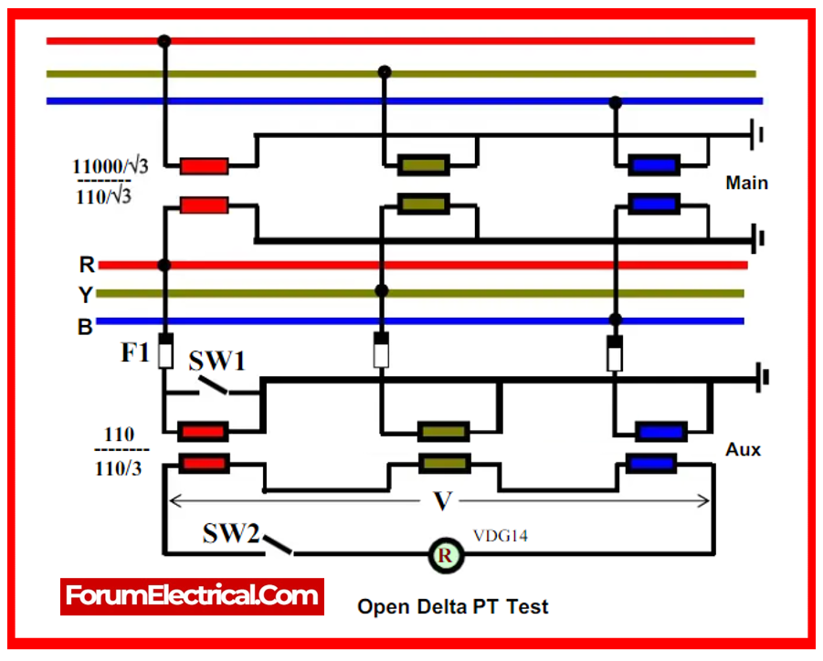
- Refer the diagram for an open delta winding test.
- Keep switches SW1 & SW2 off.
- Measure the open delta voltage ‘V’. It should be approaching zero.
- Disconnect fuse F1 on the R phase.
- Close switch SW1 to imitate V/R=0.
- Determine the open delta voltage (‘V’). It will be based on the open delta core PT ratio. For example, a PT ratio of 12kV/√3/120/3 results in an open delta voltage of 4.15V for the primary voltage of 415V.
- Repeat the test for the ‘Y’ and ‘B’ phases.

 testing procedure ensures the accuracy & reliability of voltage measurement instruments. It usually includes insulating resistance testing, ratio & polarity tests, phase angle measurements and burden tests.)
Cautions
- Check the primary fuse rating & continuity.
- Check the primary & secondary earthing. This will be firm.
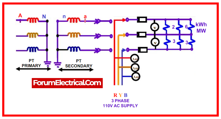
5). PT Secondary Injection Test
Procedure
- Set up the test setup according to the diagram.
- Increase the voltage eventually from 0 to 110V.
- As the voltage increases, monitor the current in each phase. This will be less than the stated ratings.
- At 110V, the secondary current should not exceed 100-150mA.
- If the current rapidly increases, verify the secondary circuit for a short.
- At full voltage, verify phase-to-phase voltage at relay/meter terminals as shown in schematic diagrams.
- To ensure proper wiring, check the phase sequence at the relay and meter terminals.
- If the same PT supply is connected to other panels, disconnect the PT secondary circuit fuses to those panels.
- Verify the voltage & phase sequence up to the fuse incoming.
- Perform PT secondary injection test for other panels from the fuse outgoing to test each panel’s PT circuit.
Cautions
- Isolate the PT secondary winding from the secondary circuit terminals to prevent the PT primary winding from becoming live because of back charging.
- Check the continuity & rating of the secondary circuit fuses.
- Perform secondary injection test step by step, removing PT fuses from other panels when the same supply is tapped.
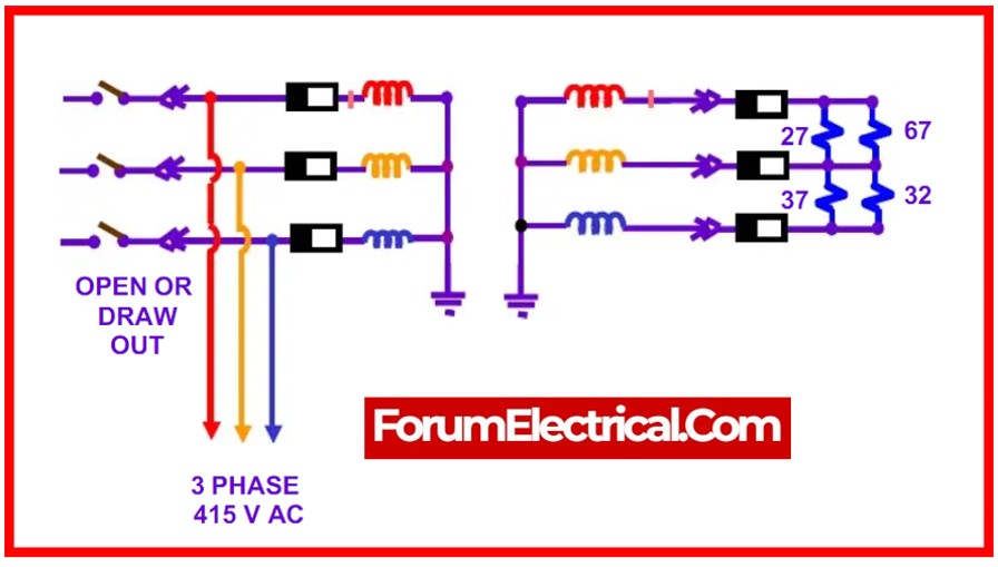
6). PT Combined Primary & Secondary Injection Test
Procedure
- Restore the connection between the PT secondary circuit and the secondary terminals.
- Restore the secondary & primary winding earthing.
- Separate PT primary from the main bus.
- Set up the test according to the diagram.
- Apply a 3 phase, 415 V supply to the PT primary.
- Measure the appropriate secondary voltage at the meter/relay terminals.
- Check the voltage across the open delta core.
- When 415V is applied to the primary winding in three phases, the voltage must be zero.
Cautions
- Firmly connect the PT primary and secondary earthing of each winding.
- Check the continuity and rating of the primary & secondary circuit fuses.
- Verify mechanical alignment of PT main (primary) pole connectors and PT earthing.
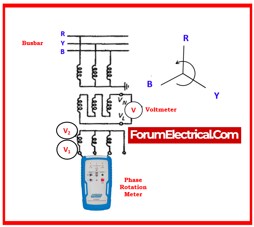
7). Phasing Test
The incoming secondary connections for a 3-phase PT or a bank of three single-phase PTs must be thoroughly tested for phasing.
While the primary circuit is active, the secondary voltages across phases & neutral must be measured to ensure that the phase connection is proper.
The phase rotation needs to be tested using a phase rotation meter attached to all three phases, as shown in the diagram.
If the three-phase PT has a damaged delta tertiary winding, check the voltage between the 2 connections from broken delta VN & VL, as indicated in diagram.
With the specified balanced 3-phase supply voltage provided to the PT primary winding, the broken delta voltage must be less than 5 volts with the rated load connected.
8). Winding Resistance Test
This test is performed to verify the winding resistance provided by the manufacturer as well as to check whether any internal winding damage in the power transformer.
Winding resistance is determined by passing a DC current across the winding & measuring the voltage drop.
Compare the reading to the factory test report.
Applicable Standard
The following standards apply to potential transformers: IS 16227-1, ANSI/IEEE C57.13 and IEC 61869-13.
Maintenance
If the following rules are followed, the risk of backfeeds is reduced, then defect analysis becomes easier.
- The drawout protection relay case structure allows for the use of a test plug. A faulty unit can be changed quickly and without disrupting service.
- Circuits must be kept as electrically separated as possible, and common connections should be avoided unless absolutely necessary for proper circuit operation.
- Each group of circuits that are electrically isolated from one another should be earthed via an independent earth link.
- When a single PT or DC supply is used to power multiple circuits, particularly that which coincides with protective equipment, each circuit should be provided via separate links or fuses. When these are removed, the circuits must be fully isolated.
- Fuses should be graded whenever possible so that a defect on a circuit that is not utilized for protection does not disrupt power to protective gear circuits.
- A single auxiliary switch should never be utilized to interrupt or close several circuits.
- When installing a relay panel, consider the access of connections because they may need to be changed if the gear is extended. Modern panels include unique test facilities, ensuring that no connections are interrupted during routine testing.
- Junction boxes must be adequately sized. If they are to be used outdoors, the boxes should be waterproof.
- All wiring needs to be ferruled for the identification.
- The supply of strong armature torque & contact pressure in relay design, jewel bearings wrapped to exclude dust, the avoidance of extremely thin wire, the use of dust tight enclosures, and so on all reduce maintenance and extend life.
What is a CT/PT Analyzer?
CT/PT Analyzer is a complete system solution for testing all types of CT/PT in accordance with IEC standards. It is a device with a good ROI (Return on Investment). The following capabilities make the CT/PT analyzer an appropriate tool for CT/PT manufacturers, testing labs, substations (up to 765kV), power plants.
Difference between Current Transformer and Potential Transformer
Difference between CT and PT
| Category | Current Transformer | Potential Transformer |
|---|---|---|
| Definition | High input current is converted to low output current. | High input voltage is converted to a low output voltage. |
| Connection | Series-connected to the instrument. | Parallelly connected to the instrument |
| Number of Turns | Primary winding has fewer turns than secondary winding. | Primary winding has a higher number of turns than secondary winding. |
| Core | Silicon steel lamination in the core. | High-quality steel with low flux densities. |
| Full line current / voltage | The full-line current is contained in the primary winding. The full-line voltage is contained in the primary winding. | The full-line voltage is contained in the primary winding. |
| Open circuit at the secondary side | The secondary winding of a current transformer cannot be left open. | The secondary winding of a potential transformer can be left open. |
| Application | Substation current measurement and protective relay operation. | Voltage measurement and protective relay operation in the substation. |
These are the major difference between CT vs PT.