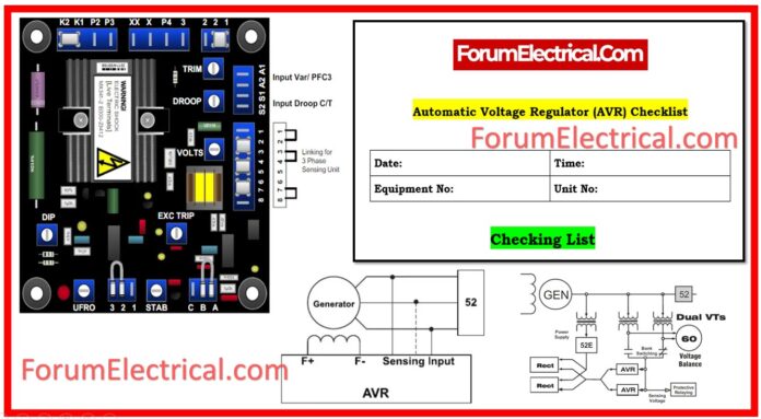
Automatic Voltage Regulator (AVR)
The Automatic Voltage Regulator (AVR) regulates the excitation current to keep the generator’s voltage output in the required range. A complete inspection of the AVR system is required to ensure its safe and effective operation.
- Automatic Voltage Regulator (AVR)
- 1). Safety Checks
- 2). Check the Auxiliary Power Supply
- 3). Power Supply & Excitation Panel Status
- 4). Bus Ducts & Cooling Systems
- 5). Check the Carbon Brush & Protection Panel
- 6). Excitation Transformers
- 7). MCB (Miniature Circuit Breaker) Function
- 8). Checks on the Alarm and Display Panels
- 9). Indications for the LDP & Mimic Panel
- 10). System Readiness
- 11). NGT Switch Position
- Checklist
The inspection activities are described in detail below:
1). Safety Checks
2). Check the Auxiliary Power Supply
3). Power Supply & Excitation Panel Status
4). Bus Ducts & Cooling systems
5). Check the Carbon Brush & Protection Panel
6). Excitation Transformers
7). MCB (Miniature Circuit Breaker) Function
8). Checks on the Alarm and Display Panels
9). Indications for the LDP & Mimic Panel
10). System Readiness
11). NGT Switch Position
1). Safety Checks
Begin by checking that there are no pending PTWs (Permits to Work) for the equipment. This makes sure the system is safe for operation and that maintenance staff are not jeopardized. In addition, ensure that no one is operating on the machinery to avoid any potential hazards during the inspection.
2). Check the Auxiliary Power Supply
Check that the Motor Control Center’s (MCC) auxiliary power supply is working properly. This is necessary to ensure that control systems & auxiliary devices function properly.
3). Power Supply & Excitation Panel Status
Ensure all power and control supplies at the excitation panel are functional. An interruption in a power supply may cause the AVR system to malfunction.
4). Bus Ducts & Cooling Systems
To avoid electrical dangers, ensure that all bus duct doors are properly closed. Check the air cooler’s cooling water system to confirm it is operational. Cooling systems are essential for avoiding the excitation system from overheating.
5). Check the Carbon Brush & Protection Panel
Check that all carbon brush contacts are working properly, as they are crucial to ensuring uniform excitation. Ensure that the generator protection panels (Panels A and B) are receiving appropriate power supply, and that the DC power supply in the Generator Transformer (GT) protection panel is turned on.
6). Excitation Transformers
Check that the excitation transformer’s cooling fan & temperature monitoring systems are working. It is essential that the excitation transformer doors be firmly closed & that the excitation transformer protection relay (also known as the GT protection relay) function properly.
7). MCB (Miniature Circuit Breaker) Function
Examine the PT cubicle MCBs to ensure that they are operational. Similarly, verify all power & control MCBs in the excitation panel to ensure they are working properly, protecting the system from electrical overloads.
8). Checks on the Alarm and Display Panels
Look for any active alarms on the Local Display Panel (LDP). Check the Mimic panel and the Distributed Control System (DCS) for any alarms, as these could indicate an issue with the AVR system. Confirm that the Generator excitation channel’s AVR (CH 01 & CH 02) is in CH 01 mode.
9). Indications for the LDP & Mimic Panel
On the LDP, check that the following indicators are correct:
- CH-1 ON: green
- AVR on: green
- EXC OFF – Red
- FCB OFF: RED
- REMOTE: yellow
Make that the system is in CH-01 mode, the AVR ON light is illuminated, & the REMOTE lamp is switched off.
10). System Readiness
After all of the checks have been done and certified as satisfactory, ensure that all systems are operational, and the system is now ready for use.
11). NGT Switch Position
Finally, make sure the Neutral Ground Transformer (NGT) Switch is closed, which completes the system’s safety tests prior to operation.
This checklist outlines a systematic approach to ensure that the AVR system is operational & that all important safety and performance standards are verified prior to usage.


