 is a device that maintains a constant voltage level in electrical equipment, ensuring consistent operation and protecting against voltage variations. It automatically changes the voltage output based on load and input variations, increasing the dependability and efficiency of electrical systems.)
")
- Automatic Voltage Regulator (AVR)
- Construction of Automatic Voltage Regulator (AVR)
- Working Principle of Automatic Voltage Regulator
- How can an AVR- Automatic Voltage Regulator be selected?
- What does three phase AVR mean?
- Is AVR capable of increasing voltage?
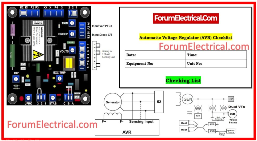
- Checklist
- Advantages of Automatic Voltage Regulator (AVR)
- Disadvantages of Automatic Voltage Regulator (AVR)
- Application of Automatic Voltage Regulator (AVR)
Automatic Voltage Regulator (AVR)
An automatic voltage regulator controls the supply voltage. The voltage is stabilized after being converted. The variation in load on the supply system is the primary cause of the voltage fluctuation. The equipment in the power system is harmed by voltage variations.
Installing voltage control instruments in various places, such as close to
- Transformers,
- Generators,
- Feeders, etc.,
will help to regulate voltage variance.
The voltage regulator is available at multiple points in the power system to regulate voltage fluctuations.
In a DC supply system, if the feeders are all the same length, the voltage can be adjusted by employing several compound generators; however, if the feeders are all different lengths, a feeder booster is used to maintain a consistent voltage at the end of each feeder. The voltage of an AC system can be regulated using a variety of techniques, including
- Booster transformers,
- Induction regulators,
- Shunt condensers, etc.
Construction of Automatic Voltage Regulator (AVR)
1). Autotransformer
A portion of the single-phase autotransformer’s winding is divided by the primary and secondary. In a two-winding transformer, the primary & secondary windings are electrically isolated, but not in the condition of an autotransformer. If the voltage increases, the AVR detects it, compares it to the reference voltage, and generates an error signal. This error signal is then sent to the servo motor via PWM signal by the Arduino.
Because the servo motor and autotransformer are connected, when the servo detects an Arduino output, both rotate automatically due to the coupling. As voltage drops at the same time as servo motors detect errors, their coupling increases voltage level, which implies that the 1-phase auto transformer in this condition functions as a BUCK BOOST system.
2). Servo motor
A servo motor is similar to a DC motor and has certain additional special purpose parts that transform a DC motor into a servo. A small DC motor & a potentiometer, a gear arrangement, and advanced electronics are all components of a servo unit. The servo rotates coupled to the main circuitry and potentiometer.
There is an output shaft on a servo motor. Sending a coded signal to the servo allowed this shaft to be moved to various angle positions. The servomotor will keep the shaft’s angular position as long as the signal is there on the input line. If the signal changes, the shaft’s angular position changes.
3). Step Down Transformer
Since the signal conditioning unit demands a low voltage level, a step-down transformer is employed to reduce 230 V to 5 V. The transformer steps down the voltage level for rectification.
4). Signal Conditioning Unit
Signal conditioning is the process of transforming an analog signal so that it satisfies the requirements for the subsequent level of processing. Analog-to-digital converters are where it is most frequently used. In the signal conditioning stage, operational amplifiers are used to carry out the signal’s amplification.
5). Arduino Kit
By connecting it, an AC mains power source can be used to power Arduino boards directly. The voltage regulator’s function is to regulate the voltage supplied to the Arduino board & maintain the DC voltages that are used by the processing unit & other components.
Working Principle of Automatic Voltage Regulator
It functions according to the principle of error detection. The output voltage of an AC power source is obtained using a potential transformer, rectified, then filtered, and then it is measured against a standard. The error voltage is defined as the variance between the actual and reference voltages. An amplifier then supplies the main exciter (or) pilot exciter with the amplified error voltage.
Therefore, the amplified error signals regulate the voltage variation by controlling the buck or boost action used to stimulate the main or pilot exciter. The primary alternator terminal voltage is controlled by the exciter output control.
How can an AVR- Automatic Voltage Regulator be selected?
The characteristics of a high-quality automated voltage regulator are listed below:
1). Voltage Regulation
2). Input Voltage Range
3). Low Impedance
4). Load Compatibility
5). Voltage Accuracy
1). Voltage Regulation
Ideal voltage control is achieved whenever the voltage value is identical to the loads that are being applied by all of the electrical equipment. The size and type of wire and cable, the transformer reactance & cables, the motor starter, the circuit design, and the power factor are a few variables that might have an impact on voltage regulation. Voltage regulation should be chosen to an accuracy of 1% regardless of these possible obstructions. By requiring it, three-phase imbalance issues are minimized and voltage variations are reduced.
2). Input Voltage Range
Defining the input voltage range is the first step in choosing the best automated voltage regulator. Because line voltages decrease more often than they increase, the input voltage range must be wide and shifting. Instead of focusing on high correction, this characteristic allows for additional low correction. Additionally, it enables the automatic voltage regulator (AVR) to be more easily configured to operate in either buck or boost mode, allowing it maximal voltage correction in severe situations.
3). Low Impedance
Impedance, which is measured in ohms, is a component’s resistance to the flow of the electrical current. Low impedance is the intended function of an (AVR) automatic voltage regulator. Low voltage, harmonic distortion, & voltage unbalance may all be turned on by interactions between the source impedance and the load current. If the automatic voltage regulator had low impedance, none of this would be necessary.
4). Load Compatibility
To ensure the specified load’s operation and prevent interference with the operation of the other loads connected to the exact same power source, voltage regulation solution must be compatible with the load. High-performance automated voltage regulators must manage all
- Power factors,
- Crest factors, and
- Loads with high starting currents.
The regulator’s response time must be developed to operate with the electronic power sources included in numerous components of modern equipment in order to prevent instability.
5). Voltage Accuracy
Increasing accuracy of voltage levels is the main function of an (AVR) -automatic voltage regulator. Critical loads impact voltage accuracy. Automatic voltage regulators typically work in circuits where changing the conductor size is unable to accomplish voltage regulation. An AVR must possess the qualities mentioned above in order to function dependably in demanding applications. Transient Suppression should also be taken into consideration as a crucial characteristic in conditions where voltage impulses, spikes, and transients are significant concerns.
What does three phase AVR mean?
A large number of three phase AVRs can also supply single phase loads. Utilizing a three phase AVR is typically more economical for three phase loads. Depending on the AVR’s design, a three-phase automated voltage regulator may control all three phases simultaneously or each phase separately.
Is AVR capable of increasing voltage?
AVR’s primary functions are as follows: It regulates and stabilizes the alternator’s voltage. It operates much like a machine in order to keep the voltage in a constant stable condition. Through the distribution of the reactive load between multiple parallel alternators, the high voltage is reduced.
Checklist
Advantages of Automatic Voltage Regulator (AVR)
- AVR contributes to attaining a steady output voltage, which protects sensitive electronics from voltage fluctuations.
- Automatic voltage regulators increase power quality and dependability.
- It reduces the influence of load variations and voltage fluctuations in the system, hence improving overall system performance.
- Automatic voltage regulators also help to reduce failures caused by overvoltage and undervoltage.
Disadvantages of Automatic Voltage Regulator (AVR)
- AVRs have a limited voltage range and may struggle to tolerate huge voltage changes, particularly under harsh conditions.
- High-quality AVRs can be costly, increasing the total system cost.
- Regular maintenance is essential to ensure proper operation, which might raise operating costs.
- Installation & configuration of AVRs can be difficult and require professional technicians.
- AVRs may not perform well with nonlinear loads, such as those present in sensitive electronics.
Application of Automatic Voltage Regulator (AVR)
- It raises the system’s excitation during fault conditions such that the maximum synchronizing power is present when the fault is cleared.
- It regulates the system’s voltage and brings machine functioning closer to stable steady state operation.
- It distributes the reactive load across the parallel-operating alternators.
- A sudden reduction of load on the system can lead to over voltages, which are decreased by automatic voltage regulators.