
- Electric Charge
- Voltage
- Electric Current
- Electrical Resistance
- Ohm’s Law
- Conductance
- Electric Power
- Power Factor
- Frequency and Time Period
- Wavelength
- Capacitance
- Inductance
- Electric Field Intensity
- Coulomb’s Law
- Gauss’s Law
- DC Generator EMF Equation
- DC Motor Back EMF Equation
- Transformer EMF Equation
- Hysteresis Loss
- Eddy Current Loss
- Transformer Turns Ratio & Transformation Ratio
- Synchronous Speed
- Efficiency
- 3-Phase Alternator EMF Equation
- Electrical Impedance
Electrical engineering is the study of
- Electric circuits,
- Power systems,
- Electrical machines,
- Power electronics,
- Control systems, and other related topics.
Formulae & mathematical equations are used in electrical engineering to describe and show the veracity of notions. These formulas and equations are very helpful in understanding the behaviour of electrical systems and in doing various computations in application.
This post provides all the electrical engineering formulas and equations that any electrical engineering student and professional must know.
Electric Charge
The subatomic quality of substances that causes them to exhibit electrical activity is known as electric charge.
Charge is symbolised by the symbol Q (or q) and is measured in Coulombs (C). Electrons and protons are the primary atomic particles that carry the electric charge, with an electron carrying a negative charge and a proton carrying a positive charge.
Electron Charge e = -1.6 X 10⁻¹⁹C
The electric charge is a quantized quantity, which implies that it always exists as an integral multiple of elementary charge (e), i.e., it is always a multiple of e.
Q=ne
where,
n=0,1,2,3,⋅⋅
Voltage
Voltage, also known as potential difference, is the difference between electric potentials of two points in an electrical circuit. The voltage is measured in Volts (V). It is also defined as the amount of work required to move (transfer) a unit charge from one point in an electric circuit to another.
Voltage(V) = Workdone(W)/Charge(Q)
To calculate voltage CLICK HERE
Electric Current
Electric current is the directed flow of electric charge, specifically electrons, through a conductor. Electric current is symbolized by I, & is measured in Ampere (A). Electrical current may alternatively be described as the charge change rate over time.
I=Q/t
To calculate current CLICK HERE
Electrical Resistance
Electrical resistance is the amount of resistance provided by a material in the flow of an electric current. It is represented as R and measured in Ohms (Ω).
R=ρla
Where,
R- Constant known as the material’s resistivity or specific resistance.
The resistivity of a material is defined as the property by which it opposes (resist) the flow of current through it.
Ohm’s Law
Ohm’s law is a fundamental electrical circuit law.
It states that the current flow through a conductor is directly proportional to the voltage across the conductor and inversely proportional to the resistance of the conductor, where the temperature remains constant.
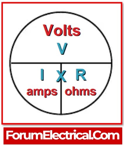
It expresses the connection between a conductor’s voltage, current, and resistance as,
V=IR
To calculate voltage CLICK HERE
Conductance
The measure of ease that a material provides in the path of current is known as conductance, and it is given as the reciprocal of electrical resistance.
G=I/R=a/ρl=σa/l
Where,
σ – Conductivity of the material and
Conductivity,σ=1/ρ
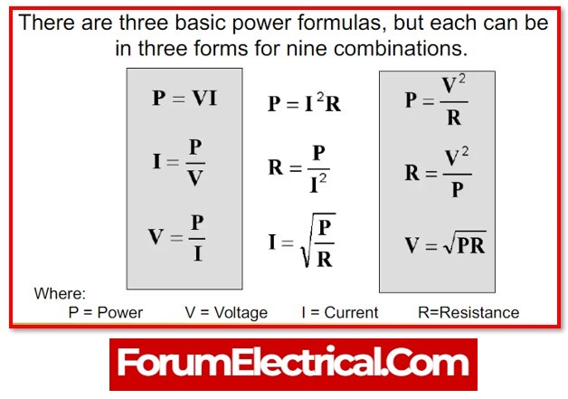
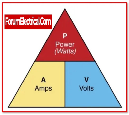
Electric Power
Electric power is the rate of accomplishing work in an electric circuit. It is represented by P & measured in watt (W).
To calculate power CLICK HERE
In DC circuits,
Power (P) =VI
Power (P) =I2R
Power (P)=V2/R
In 1-phase AC circuits,
Active power P=VIcosϕ
Reactive power Q=VIsinϕ
Apparent power S=VI
Where,
Active power – measured in watts – W,
Reactive power – measured in volt-amperes reactive – VAr and
Apparent power – measured in volt-amperes – VA.
In 3-phase AC circuits,
Active power P=3VpIpcosϕ
Active power P=3√VLILcosϕ
Reactive power Q=3VpIpsinϕ
Reactive power Q=3√VLILsinϕ
Apparent power S=3VpIp
Apparent power S=3√VLIL
Power Factor
Power factor is measure of utilisation of electric power in an ac (alternating current) electric circuit. It provides information (detail) about the part of total power utilised by load in an electrical system. It can be calculated using the ratio of the active power to the apparent power.
Powerfactor (cosϕ) =Activepower(P)/Apparentpower(S)
The power factor of an electrical load (load) varies from -1 to 1. It is leading for capacitive loads, lagging for inductive loads, and unity (1) for resistive loads.
Frequency and Time Period
The frequency of a quantity is the number of cycles that an alternating quantity completes in one second.
It is symbolised by the letter f & is measured in Hertz (Hz).
f=Number of cycles/time
The time it takes an alternating quantity to complete one cycle is defined as its time period. It is symbolised by the letter T and is timed in seconds (s).
An alternating quantity’s frequency is inversely proportional to its time period.
f∝1/T
Wavelength
The wavelength of a signal is the distance between two successive crests in neighbouring (adjacent) cycles of an alternating quantity. It is symbolised by the Greek letter Lambda (λ).
λ=u/f
Where,
v – Wave velocity &
f – Frequency
Capacitance
The ability of a material to store electric charge in the form of an electrostatic field is known as capacitance.
The capacitor is the circuit element that is utilised to introduce the capacitance effect in an electric circuit.
C represents capacitor capacitance and is measured in Farads (F).
A capacitor’s capacitance is given by,
C=Q/V
Where,
Q – Electric charge stored on each capacitor plate &
V – Voltage across the capacitor plates.
A capacitor’s capacitance may also be expressed in terms of its physical dimensions as,
C=ϵA/d
Where,
ϵ – Permittivity of the medium between plates
A – Area of the cross-section of the capacitor plate, &
d- Distance between the capacitor’s plates.
Inductance
Inductance is a material property that allows it to store electrical energy in the form of a magnetic field. The element is referred to as an inductor. L represents inductance and is measured in Henry (H).
It is provided by the magnetic flux linkage to current ratio as,
L=Nϕ/I
Where,
N – Number of turns in the inductor coil and
Φ – Magnetic flux
Electric Field Intensity
The electric field is the region surrounding an electrically charged substance in which a test charge generates (experiences) a force of attraction or repulsion.
The strength of the force acting on the charge in the field is referred to as electric field intensity.
It is represented by the letter E & is measured in Newton per coulomb (N/C).
E=F/Q
Coulomb’s Law
The Coulomb’s law is a basic rule of electrostatics that explains that the electrostatic force operating between two charges is directly proportional to the product of their magnitudes and inversely proportional to the square of their distance.
F∝Q1Q2/d2
F=k (Q1Q2/d2) = (1/4) (Q1Q2/d2)
Where,
Q1 and Q2– Static charges, and
d – Distance between them.
Gauss’s Law
The value of electric flux is given by Gauss’ law of electrostatics, which is,
ϕe=Q/ϵ
DC Generator EMF Equation
The emf produced by a direct current generator is given by,
Eg=NPϕZ/60A
Where,
N -Armature’s rotational speed,
P – Number of field poles,
ϕ- Magnetic flux per pole,
Z – Number of armature conductors, and
A – Number of parallel routes.
DC Motor Back EMF Equation
Back emf or counter emf is the emf produced in a dc motor by electromagnetic induction. It is provided by,
Eb=NPϕZ/60A
Transformer EMF Equation
The formula that yields the value of emf induced in a transformer’s windings is known as the emf equation. It is provided by,
E=4.44fϕmN
Where,
f – Alternating current supply frequency,
m – Maximum flux, &
N – Number of turns in the winding.
Hysteresis Loss
The power loss in the iron core of electrical equipment (motors, generators, transformers, and so on) caused by magnetic reversal is known as hysteresis loss, and it is computed as follows:
Ph=ηBm1.6fV
Where,
η – Hysteresis coefficient,
Bm– Maximum flux density in the core,
V – Volume of the core, and
f – Magnetic reversal frequency.
Eddy Current Loss
The power loss caused by eddy currents created in machine iron cores is known as eddy current loss and is given by,
Pe=keBm2f2t2V
Where,
ke– Constant and
t – Thickness of each core lamination.
Transformer Turns Ratio & Transformation Ratio
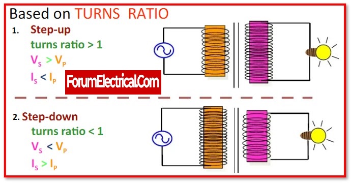
A transformer’s turns ratio is defined as the ratio of the number of turns in the main winding to the number of turns in the secondary winding, i.e.
Turns ratio=N1/N2=E1/E2=V1/V2=I2/I1
A transformer’s transformation ratio is defined as the ratio of output voltage to input voltage,
Transformation ratio=V2/V1=E2/E1=N2/N1=I1/I2=1a

Synchronous Speed
The magnetic field in spinning electric equipment such as motors and generators revolves at a consistent pace known as synchronous speed.
Ns=120f/P
Where,
f – Supply frequency and
P – Machine’s field poles.
Efficiency
The ratio of output power to input power for an electrical machine is known as machine efficiency.
Efficiency,η=Output power(Po)/Input power(Pi)
3-Phase Alternator EMF Equation
The magnitude of the produced (generated) EMF is given by the EMF equation of a three-phase alternator. EMF generated per phase is,
Eph=2.22kpkdfϕZ=4.44kpkdfϕT
Where,
kp– Armature winding pitch factor
kd– Distribution factor
Z – Number of conductors per phaseand
T – Number of turns per phase.
Electrical Impedance
Impedance is the combined opposition generated by resistance, inductance, and capacitance in the flow of electric current in alternating current circuits.
It is represented by the letter Z and measured in Ohms (Ω).
Z=R+jX
Where,
X – Reactance- Opposition provided by the inductor or capacitor.
In the case of an inductor,
Inductive reactance (XL) =ωL=2πfL
In the case of a capacitor,
Capacitive reactance (XC) =1/ωC=1/2πfC
In this post, a listing of all the essential equations and formulas in fundamental electrical engineering may be found. In addition, also included a definition for each quantity for reference.
Since they are used in a wide range of electrical calculations, each and every electrical engineer has to be familiar with each of these formulas.
