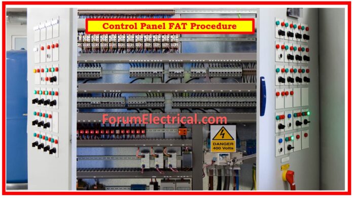
Purpose
To establish acceptable standards for accepting product manufacturing quality and ensuring control panel installation quality.
Scope
Acceptance testing at the factory and on-site.
Responsibility
QA/QC will observe the factory acceptance test.
Reference Document
Procedure
Factory Acceptance Test (FAT) for Control Panel
All factory acceptance test (FAT) observations must be documented on the material quality inspection report.
Control Panel
The components used in the control panel must meet the applicable IEC standards.
The components must be appropriate for the specific application in terms of the external design of the assembly (control panel) (e.g., open or enclosed), rated voltages & rated currents, service life, making & breaking capacities, short-circuit withstand strength, etc.
Components with a short circuit withstand strength &/or a breaking capacity insufficient to withstand the forces predicted to occur at the installation site must be safeguarded by means of current-limiting protective devices, such as fuses or circuit breakers.
When selecting current-limiting protection devices for integrated switching devices, the maximum allowable values stated by the device manufacturer must be considered, with due attention for coordination.
Coordination of components, such as motor starters with the short-circuit safety devices, must adhere to the applicable IEC requirements.
Type Test
Type tests are designed to verify compliance with the standards outlined in this standard for specific types of assembly.
Type testing will be performed on a sample of such an assemblies or pieces of such an assembly that are manufactured to the same or similar design.
Type tests involve verifying temperature rise restrictions.
- Verification of dielectric characteristics.
- Verification of short-circuit strength.
- Checking the continuity of the protection circuit.
- Verification of clearances & creepage distances.
- Verification of the mechanical operation.
- Verification of the level of protection.
These tests can be performed in any order &/or on multiple samples of the identical type.
Routine Test
Routine testing are designed to detect defects in materials & workmanship. They are performed on every new assembly following its assembly (or) on each transport unit. Another routine test at the site of installation is not necessary.
Assemblies assembled from standardized components outside the manufacturer’s works, using only parts & accessories specified (or) supplied by the manufacturer for this purpose, must be routinely tested by the firm that assembled the assembly.
Routine tests include: Inspection of the ASSEMBLY, including wire inspection & if necessary, electrical operation testing and dielectric testing.
Equipment for testing: HV tester: (0-5 KV)
Testing Procedure: The test voltage should be applied between all live elements and the ASSEMBLY’s interconnected exposed conductive parts, as well as between each pole and all other connected poles for this test.
The test voltage at the time of application may not exceed 50% of the values listed in the test voltage selection table below. It will then be gradually increased over a few seconds to the full value given in the table and held for 60 seconds.
The alternating current power sources must have enough power to maintain the test voltage notwithstanding any leakage currents. The test voltage must have a nearly sinusoidal waveform with a frequency across 45 and 62 Hz.
Selection of Voltage (Test Volt):
For Primary Circuits:
| Rated Insulation Voltage Ui (V) | Dielectric Test Voltage (AC)(RMS)(V) |
| Ui ≤ 60 V | 1000 V |
| 60 V < Ui ≤ 300 V | 2000 V |
| 300 V < Ui ≤ 660 V | 2500 V |
| 660 V <Ui ≤ 800 V | 3000 V |
| 800 V< Ui ≤ 1000 V | 3500 V |
| 1000 V <Ui ≤ 1500 V ( for DC only) | 3500 V |
For Auxiliary Circuits:
| Rated Insulation Voltage Ui (V) | Dielectric Test Voltage (AC)(RMS)(V) |
| Ui ≤ 12 V | 250 V |
| 12 V< Ui ≤ 60 V | 500 V |
| Ui> 60 V | 2 Ui + 1000 with a minimum 1500V |
If there are no punctures or flash-overs, the test is declared passed.
Checking Protective Measures and Circuit Continuity
- Ensure continuity of the protective circuits by direct linkages or protective conductors.
- When part of the assembly is removed from enclosure for routine maintenance, the protection circuits for the rest will not be disturbed.
- If precautions are taken to ensure permanent good conductivity & a current carrying capacity sufficient for withstanding earth fault current in the assembly, means used to assemble metal parts are sufficient for ensuring continuity of protective circuits.


