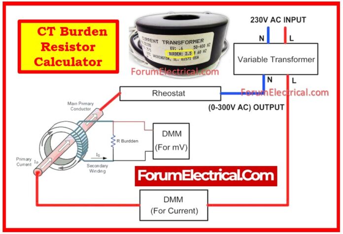
Calculator
Click here for more Electrical Calculators
What is a CT Burden Resistor?
A CT burden resistor is a precision resistor that connects to the secondary terminals of the Current Transformer (CT) to provide a specified load (burden) for accurate current transformation and signal processing.
It is important for ensuring that the CT functions within its rated parameters & produces consistent, linear output.
In most low-voltage applications, such as electronic energy meters (or) monitoring systems, CTs (particularly voltage output types like 0.333 V) require a matching burden resistor to convert secondary current into a measured voltage across the resistor.
The CT burden resistor will be connected between the current transformer terminals S1 and S2.
The burden resistor’s primary function is to safeguard the current transformer during open circuit conditions.
As previously stated, the secondary of a current transformer should always be closed to prevent excessive voltage rise in second terminal.
During certain conditions, such as a loose connection, soldering failure, cable failure, and so on, the CT terminal will be opened and a high voltage will be created across the CT secondary terminal.
The high voltage degrades the insulation of CT-current transformer.
Function of CT Burden Resistor
- A burden resistor converts CT (Current Transformer) secondary current into a voltage signal for measurement or monitoring.
- Avoids CT saturation by maintaining the burden within the rated limits.
- Maintains system safety & measurement accuracy. It includes different types of CTs
Types of CTs
- Current Output CTs (Ex: 5A, 1A): The burden is measured in VA (volt-amperes) & includes the impedance of the wiring and associated devices.
- Voltage Output CTs (Ex: 0.333V RMS): These require a load resistor to convert current into voltage, which must be suitably sized.
Purpose of CT Burden Resistor
- The CT Burden Resistor generates a voltage signal proportional to current being measured.
- To make sure the CT is linear and accurate.
- To avoid open-circuiting the CT secondary, that could result in dangerously high voltages & core saturation.
- To match the CT’s rated output voltage and current to specific applications (e.g., 100 A primary and 0.333 V output).
Why is a Burden Resistor required?
To prevent such damage to the insulation/current transformer, burden resistors are utilized.
Under normal conditions, it functions as a dummy resistor, with no current flowing through it.
During the abnormal condition (secondary open condition), a high voltage is supplied across the resistor, causing current to flow through it.
The burden resistor can prevent CT insulation failure.
At same time, the burden resistor raises the voltage across the CT terminal.
We must select the resistor value carefully because increasing the resistor value raises the voltage across the CT.
It is also used to compute the burden resistance value to achieve the best current-to-voltage ratio not like Ohm’s law.
At the same time, reducing burden resistance lowers the CT’s secondary output voltage.
Any CT (Current Transformer) secondary terminal needs to be connected to the burden resistor at all times, regardless of the primary current flow.
What is CT Burden Resistor Calculator?
A CT Burden Resistor Calculator is an online calculator that computes:
- The required burden resistance (in ohms) according to CT requirements.
- The power drawn by the resistor (in watts).
- Whether the connected burden remains within CT’s rated capacity.
Formula
To Calculate Burden Resistor (R)
R = (VCT X N) / IP
Where
R – Burden Resistor (Ω)
VCT – CT Rated Output Voltage (V)
IP – CT Rated Primary Current (Amps)
N – CT Turns Ratio
To Calculate Power Dissipation (P)
P = [VCT X (IP/N)]
Where
P – Power Dissipation (Watts)
VCT – CT Rated Output Voltage (V)
IP – CT Rated Primary Current (Amps)
N – CT Turns Ratio
Solved Example
How can you determine the burden resistor value & power dissipation for a CT with a 100 A primary current, 0.333 V output, & 3000:1 turns ratio?
Given:
IP – 100 A
VCT – 0.333 V
N – 3000
Solution:
R = (VCT X N) / IP
R = (0.333 X 3000)/ 100
R = 9.99 ≈ 10 Ω
P = [VCT X (IP/N)]
P = [0.333 x (100/3000)]
P = 0.0111 W
Answer:
R = 10 Ω
P = 0.0111 W
A CT burden resistor guarantees appropriate voltage development in the voltage-output CTs.
A CT burden resistor calculator makes it easier to select the right resistance while also ensuring safe power ratings.
Using the improper burden might result in CT inaccuracy, saturation, and equipment damage.


