
- What is Current Transformer?
- Current Transformer Construction
- Components of Current Transformer
- Current Transformer Working Principle
- Current Transformer Specification
- Current Transformer Types
- Indoor Current Transformer
- Outdoor Current Transformer
- Bushing Current Transformer
- Portable Current Transformer
- Current Transformer Phasor Diagram
- Current Transformer Ratio & Phase Angle Errors
- Advantages of Current Transformer
- Disadvantages of Current Transformer
- Applications of Current Transformer
- Difference between Current Transformer and Potential Transformer
- Calculator
- Why is CT Secondary Side never an effective option to keep Open?
- What does “CT Polarity” refer to?
- Frequently Asked Questions
What is Current Transformer?
A current transformer is an instrument used to convert current from a greater value to a lower value in a proportionate value. The ammeter can securely monitor the high current flowing through the transmission lines because it converts the high voltage current to low voltage current.
When the current to be measured is so great that the meter (or) instrument coil cannot easily be manufactured of sufficient current carrying capacity, the current transformer is employed with the AC instrument, meters, or control equipment.
The current transformers have equal primary and secondary currents. Due to the difficulties of insufficient insulation within the meter itself, the high voltage current is measured via a current transformer. Meters that measure current up to 100 amps require a current transformer.
Current Transformer Construction
The current transformer core is made of silicon steel lamination. For manufacturing cores with a high degree of accuracy, Permalloy or Mumetal is employed. The current to be measured is carried by the current transformer’s primary windings and is linked to the primary circuit. The transformer’s secondary windings carry the current is directly proportional to the current to be measured, & they are connected to the current windings of the meters or instruments.
The primary and secondary windings are separated from the cores and from one another. The primary winding is a one-turn winding (also known as a bar primary) that carries the whole load current. The transformers’ secondary winding features a huge number of turns.
The circuit’s current transformer ratio is the ratio of the primary current to the secondary current. The transformer’s current ratio is typically high. The secondary current ratings are in the 5A, 1A, and 0.1A range. Current primary ratings range from 10A to 3000A or higher.
Components of Current Transformer
1). Primary Ampere Turns
Because current transformers carry a large amount of current, the total number of primary ampere-turns typically ranges from 5000A to 10000A.
2). Core
To attain low magnetising ampere variations the core material must have low iron losses and reluctance. Fundamental materials such as nickel and iron alloys have various properties such as low loss & high permeability.
The transformer core can be constructed with silicon steel lamination. The primary winding of the transformer, which carries current, is connected to the major circuit. Secondary winding current is proportional to primary winding current and is linked to meters or other equipment.
The primary & secondary windings are separated from the cores. The primary winding’s one turn carries the entire load current, but the secondary winding contains numerous turns.
A current transformer ratio is the ratio between primary & secondary currents. The current ratio of the transformer is normally high. The secondary winding currents are rated at 0.1A, 1A, and 5A, while the primary current ratings range from 10A to 3000A.
3). Windings
Positioning the windings close together reduces the transformer’s leakage reactance. In the primary winding, copper strips are utilized as wires, & SWG wires are utilized in the secondary winding. These windings can be constructed with appropriate strength and fixed bracing without causing any problems.
4). Insulation
Varnish and tape are used to insulate the transformer’s windings. The insulation arrangements necessary for high-voltage applications absorb the oil used in the windings.

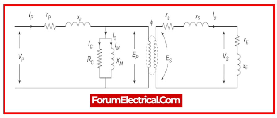
Current Transformer Working Principle
The operating concept of a current transformer differs from that of a standard voltage transformer. It, like the voltage transformer, has two windings. The secondary winding induces alternating current. When alternating current is passed via the primary winding, an alternating magnetic flux is generated. This type’s load impedance is relatively low. As an outcome, this transformer is in a state of short circuit. As a result, the secondary winding’s current is determined by the primary winding’s current but is unaffected by the load impedance.
The Effect of a Secondary Winding Open Circuit
A CT’s secondary winding is connected to its burden and is always closed during the normal operation. Because the ampere-turns of each winding are equal & opposing, the current always goes through the secondary windings as well as the primary windings.
The secondary turns will be 1% to 2% different from the primary turns, with the difference used to form the magnetizing core. If the secondary winding is opened & the current passes via the primary windings, there will be no demagnetizing flux caused by the secondary current.
Because the secondary loses the counter ampere turns which it normally possesses, the uncontrolled primary MMF will create an excessively large flux in the core. This flux will cause core loss with additional heating, & a high voltage will get induced across the secondary terminal.
This voltage induced the insulation to dissolve and may result in future accuracy loss due to the high MMF causing residual magnetism in the core. As a result, the secondary CT should never remain open if the main is conducting current.
Current Transformer Specification
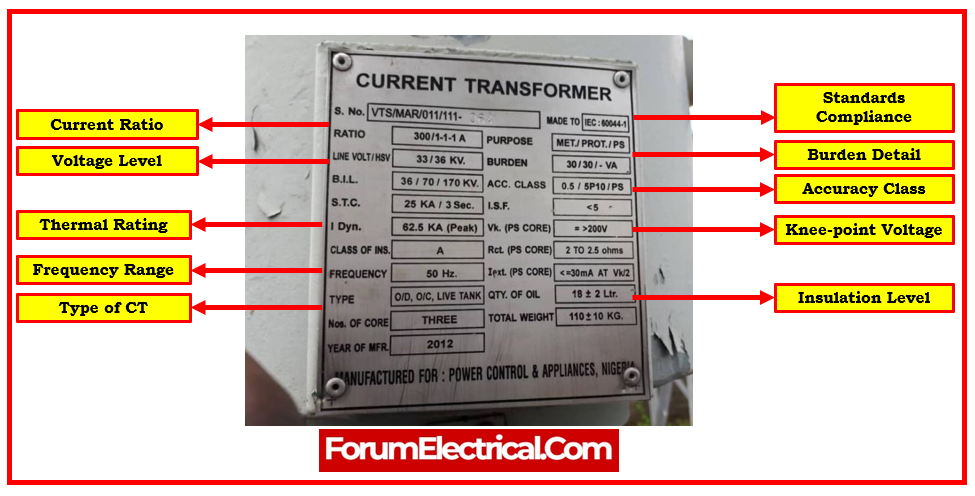
Current Rating: The highest primary current that current transformer can correctly measure is specified by the current rating.
Turns Ratio: This is the ratio between the transformer’s primary and secondary currents.
Accuracy Class: This class specifies the level of precision in measuring primary current & is usually expressed as a percentage.
Burden: The greatest load that can be supplied to the secondary winding without impacting the current measurement’s accuracy.
Frequency Range: This parameter specifies the frequency range in which the current transformer (CT) can deliver accurate measurements.
Insulation Level: Defines the maximum voltage that the current transformer may withstand without causing insulation breakdown.
Thermal Rating: The maximum continuous current that transformer may handle without exceeding the prescribed temperature rise.
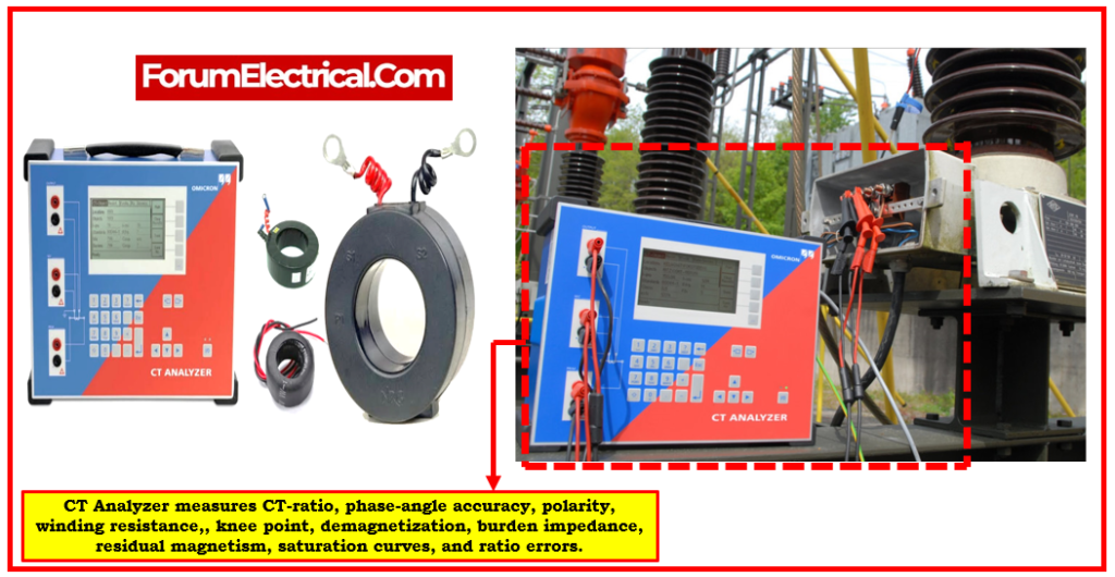
Knee-Point Voltage: The voltage level that indicates when the current transformer starts to saturate & differ from linearity is specified as the knee-point voltage.
Phase Angle Error: The angular difference between primary and secondary currents is shown by the phase angle error.
Accuracy at Varied Loads: This parameter specifies the accuracy of current transformer at different levels of load conditions.
Standards Compliance: Indicates whether the current transformer complies with relevant industry standards such as IEC, ANSI, or IEEE.
Current Transformer Types
Current transformers are classified into two types.
A measuring current transformer is one of the equipment used to measure current, energy, & power magnitude.
A protective current transformer, on the other hand, is utilized when combined with relays, trip coils, & other types of protective equipment. The various types of current transformers are as follows:
Current transformers are classified into four categories.
- Indoor Current Transformer
- Outdoor Current Transformer
- Bushing Current Transformer
- Portable Current Transformer
Indoor Current Transformer
For indoor-type transformers, low voltage circuits are typically preferred. There are various types of them, including
- Wound type,
- Window type, &
- Bar type.
The wound type, like the basic type, has two windings, such as the primary and the secondary. These are beneficial in summarizing applications due to their high primary ampere variation values and good reliability.
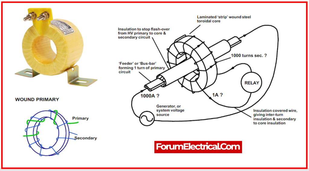
- Wound Type
The wound type, depending on the design, consists of two separate windings (primary & secondary) on a magnetized steel core. It is very similar to a standard current transformer.
- Bar Type
The bar-type transformer’s primary & secondary cores are formed of bars. The primary bar is an important part of this design. The magnetism in the core of the transformer has the potential to degrade accuracy. Window-type transformers can be placed near the primary conductor since they can be constructed without a primary winding.
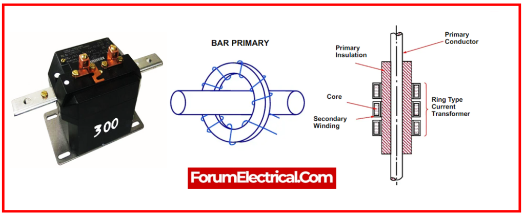
- Window (Toroidal) Type
Instead of the primary winding, a conductor carrying the primary load current is passed through the opening in core of a window-type device.
These transformers come in both solid-core and split-core variations.
Split-Core Transformer: Split-core transformers can be positioned close to the conductor without separating it.
Solid-Core Transformer: A solid-core transformer, on the other end, needs the primary conductor to be detached before joining.
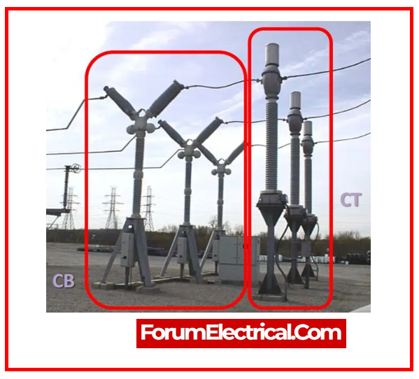
Outdoor Current Transformer
Outdoor-current transformers are used in high voltage circuits such as substations and switchyards. There are two types:
- Gas-insulated Current Transformer and
- Oil-filled Current Transformer.
Gas-Type Current Transformer: These current transformers are insulated with a gas such as SF6. They are typically utilized in high-voltage power systems & are sealed to keep out the elements. They have a small size and are ideal for settings with limited space.
Oil-Filled Current Transformer: These current transformers are commonly utilized in high-voltage power systems and are filled with oil. The oil acts as insulation and cooling, as well as protecting the CT from environmental factors such as moisture & dust.
Bushing Current Transformer
Because the secondary & core are close to the primary conductor, this transformer is similar to the bar type. The secondary winding of the transformer can be turned into a circular core, rather than an annular one. It connects to a high-voltage bushing in
- Switchgear,
- Power transformers,
- Circuit breakers, or
- Generators.
The conductor serves as the primary winding after passing through the bushing, & the core can be organized by enclosing the core with an insulating bush. Because of their low cost, these types of transformers are used for relaying in high-voltage circuits.
Portable Current Transformer
This high-precession transformer is commonly used in conjunction with high-precision ammeters & power analysers. These transformers can be found in split core, clamp ON portable, & flexible configurations. The measuring current range of portable CTs is 1000 to 1500 A. These transformers are mostly used to protect measuring instruments from high-voltage circuits.
Current Transformer Phasor Diagram
The current transformer’s phasor diagram is depicted in the figure below. As a starting point, the primary flux is used. Primary & secondary induced voltages are 90º behind the main flux.
The primary and secondary voltages’ magnitudes are determined by the number of turns on the windings. The components of the magnetizing & working current induce the excitation current.
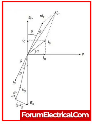
Where,
Ep– Primary induced voltage
Es-Secondary induced voltage
Ip -Primary current
Is– Secondary current
Kt– Turn ratio, (NS/NP)
Φs – Main flux
Iw– Working component
I0– Excitation current
Im-Magnetizing current
Current Transformer Ratio & Phase Angle Errors
There are two errors in the current transformer:
- Ratio error and
- Phase angle error.
Current Ratio Error: The current transformer is mostly caused by the energy component of the excitation current & is given as
Ratio Error = (Kt Is– Ip)/Ip
Where,
Ip -Primary current
Is– Secondary current
Kt– Turn ratio, (NS/NP)

Phase Angle Error: The vector angle between the primary & reversed secondary currents in an ideal current transformer is zero. However, there is a phase difference between the primary & secondary currents in a current transformer because the primary current additionally supplies the component of the exciting current. The difference between the 2 phases is thus referred to as a phase angle error.
Advantages of Current Transformer
- Large currents are able to be safely measured.
- These isolate the high-current line from measuring instruments (such as voltmeters and ammeters).
- Controls the operation of protective equipment such as pilot lights & relays.
- A single current transformer can power multiple instruments.
Disadvantages of Current Transformer
- Only measures alternating current.
Applications of Current Transformer
- Current measurement in industrial revenue metering applications.
- High-voltage line and electrical substation protection equipment.
- AC-DC filters and current converter uses in substations.
- In capacitive banks, it is used as an integrated (embedded) protection module.
- Used to measure current in handheld instruments such as AC clamp meters.
Difference between Current Transformer and Potential Transformer
Difference between CT and PT
| Category | Current Transformer | Potential Transformer |
|---|---|---|
| Definition | High input current is converted to low output current. | High input voltage is converted to a low output voltage. |
| Connection | Series-connected to the instrument. | Parallelly connected to the instrument |
| Number of Turns | Primary winding has fewer turns than secondary winding. | Primary winding has a higher number of turns than secondary winding. |
| Core | Silicon steel lamination in the core. | High-quality steel with low flux densities. |
| Full line current / voltage | The full-line current is contained in the primary winding. The full-line voltage is contained in the primary winding. | The full-line voltage is contained in the primary winding. |
| Open circuit at the secondary side | The secondary winding of a current transformer cannot be left open. | The secondary winding of a potential transformer can be left open. |
| Application | Substation current measurement and protective relay operation. | Voltage measurement and protective relay operation in the substation. |
These are the major difference between CT vs PT
Calculator
Why is CT Secondary Side never an effective option to keep Open?
A current transformer’s secondary winding must never be left open. A current transformer’s secondary winding is not supposed to be open circuited while the primary winding of the transformer is carrying current. The MMF generated by each winding is equal & opposite when a current passes through the primary and secondary windings, respectively.
The magnetic flux in the CT core can then achieve a value that is controlled only by the primary MMR when the secondary winding is opened normally, eliminating the opposing MMF that the secondary was generating. It causes a significant increase in the flow in the core, which has the following negative effects:
- The increasing flux can saturate the CT’s magnetic core, leaving it with a significant amount of residual flux & potentially significantly reducing accuracy going further.
- A rapid rate of flux rise in the core causes the current transformer’s open circuit secondary winding to experience a high voltage. This high voltage could be enough to endanger human life and cause the insulation to fail.
If one need to remove a meter from a CT’s secondary circuit. The secondary must be shorted out before one can remove the meter. Once the secondary circuit is once more closed, the secondary winding short circuit may be eliminated.
What does “CT Polarity” refer to?
The term “same polarity end” refers to either the two endpoints of a circuit that reaches a high potential at the same time (or) the end that reaches a low potential at the same time. Current transformer (CT) polarity is the direction of current between its primary and secondary windings.
Frequently Asked Questions
1). Why are current transformers used?
- Power system current measurement and monitoring.
- Protection against overcurrent and faults in electrical equipment.
- Metering and billing of energy in utility applications.
- Detection of ground faults in electrical systems.
- Protection for the motor and generator.
- Analysis and monitoring of power quality.
- In industrial automation & control systems, current sensing is used.
- In electrical protection methods, current-based relay operation is used.
- Electrical load monitoring and control.
- Monitoring of renewable energy installations.
2). How does a current transformer work?
The current of a different circuit is measured using a Current Transformer (CT). CTs are utilized all around to monitor high-voltage wires that connect national power grids. A CT is designed to generate alternating current in the secondary winding that is proportionate to the current measured in its primary winding.
3). What is the accuracy class of a current transformer?
Accuracy class specifies the level of precision in measuring primary current & is usually expressed as a percentage in current transformer.
4). What are the primary and secondary ratings of a CT?
This value is plainly equal to the ratio of primary & secondary coil turns. A CT’s current ratio is typically high. Typical secondary current (IS) ratings are 5A, 1A, and 0.1A. The associated primary current ratings range from 10A to 3000A (or) higher.
5). How do I select the right CT for my application?
The following parameters must be considered before selecting the appropriate current transformer (CT) for an application:
- Rated load on secondary side,
- Accuracy class rating,
- The circuit’s voltage,
- Rated primary current,
- Rated secondary current.
6). What is the burden of a CT?
Burden is the greatest load that can be supplied to the secondary winding without impacting the current measurement’s accuracy in the current transformer.
7). What is the saturation of a CT?
The CT is considered “saturated” when it can no longer output the appropriate quantity of current. Applying an AC voltage to the CT’s secondary winding and gradually increasing it until saturation is achieved is how saturation is tested.
8). Can CTs be used for DC current measurement?
Using additional AC excitation and the fluxgate principle to detect the second harmonic of the excitation frequency, existing CTs are able to measure DC currents with an accuracy of 5%.
9). What are the safety considerations when working with CTs?
Because the current transformer is employed to measure high currents, the following precautions must be considered when utilizing:
- The current transformer secondary should never be open-circuited.
- If the ammeter attached in the secondary is to be removed from the circuit, the secondary terminals must initially be short-circuited by the low resistance of less than 0.5Ω.
- A short-circuiting switch must be installed across the secondary end terminals of the current transformer.
- Because current transformers are utilized in high voltage lines, oil cooling is required.
- To reduce the risk of shock to the operating staff, the secondary end of the CT-current transformer must be earthed.
- They cannot be used above their rated current.
- The current transformer’s primary winding must be as compact as possible.
- The current transformer secondary should be constructed to carry a 5A current.
10). What is the ratio of CT or CT ratio?
The ratio of the primary current input to the secondary current output when the load is at its maximum or at full load is known as CT ratio.
Ex: Ratio-300:5
Primary Side: 300 A
Secondary Side: 5 A