Purpose
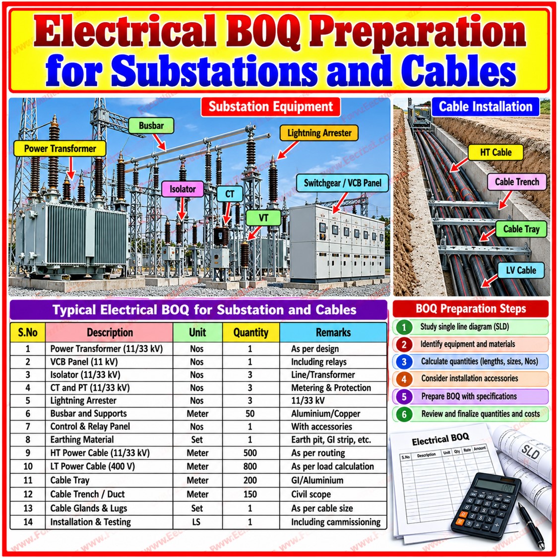
This post analyses the Electrical Bill of Quantities (BOQ) for the substation and cable works of a substation layout development.
The scheme takes 11 kV supply from a tapping point on the network, routes it through ring main units and 11 kV underground cable to seven 250 kVA transformer substations and distributes power at 415 V through feeder pillars to 34 individual plots and 107 street-light points.
All major equipment is to follow network specifications.
The rate and amount columns are blank, so this review covers quantities, technical content and internal consistency only, not cost.
Summary of Principal Quantities
| Item | Unit | Qty | Remark |
|---|---|---|---|
| 4-way RMU | Set | 2 | Incomer/outgoing 630 A, SF6 VCB, DAS, E/F and O/C |
| 15-way RMU | Set | 1 | Same electrical description as 4-way item |
| Double pole structure, 11 kV | Set | 1 | 2 x 400 A GOS, 9 m RCC pole |
| 3.5C x 240 sq.mm LT UG cable | m | 4,850 | 1.1 kV XLPE, Al, armoured, in hume pipe |
| 4C x 10 sq.mm UG cable | m | 5,180 | Street-light and service runs |
| Terminations 240 / 10 sq.mm | No. | 84 / 220 | Compression gland and lugs |
| Feeder pillar, plot type | No. | 34 | 2 x 250 A switches, loop-in loop-out |
| Feeder pillar, 6 x 250 A MCCB | Set | 1 | 300 A Al busbar |
| Feeder pillar, 4 x 250 A MCCB | Set | 2 | As above; quantity is inferred from the sheet |
| 250 kVA, 11/0.433 kV transformer | Set | 7 | Oil cooled, floor mounted |
| 11 kV 3C x 240 sq.mm XLPE cable | m | 1,350 | IS 7098 Part II |
| HT straight-through joint kits | No. | 4 | 240 sq.mm |
| HT terminations / pot heads | No. | 14 / 2 | Pot heads at GOS tapping point |
| Street-light poles, 70 W fixture equipment | No. | 107 | Fixture and gear box also 107 each |
| Cable trench excavation | cum | 2,110 | All kinds of soil |
| Earth pits (GI pipe / copper plate) | No. | 68 / 7 | Plus earthing strip, lump sum |
| 200 mm DWC pipe, road crossings | Rmt | 750 | Cable ducting |
| Inspection chambers 450 mm cube | No. | 34 | One per plot pillar |
| 50 mm uPVC pipe for service mains | Rmt | 13,300 | 6 kg pressure |
| Chain-link fencing | Rmt | 95 | Per substation |
System Architecture
The power path runs in 5 stages.
Stage-1
First, the 11 kV supply is tapped through a double pole structure carrying two 400 A group operating switches on a 9 m RCC pole.
Stage-2
Second, 1,350 m of 11 kV, 3 core, 240 sq.mm XLPE cable carries the supply from the tapping point to the ring main units.
Stage-3
Third, the 4-way and 15-way RMUs provide switching, protection and ring feed to the transformers.
Stage-4
Fourth, seven 250 kVA, 11 kV/433 V transformers step the voltage down.
Stage-5
Fifth, 3.5 core 240 sq.mm LT cables feed the feeder pillars which supply the plots and the street-light network.
Total installed transformer capacity is 7 x 250 = 1,750 kVA.
The rated full-load current (FLC) of one 250 kVA transformer is about 13 A on the 11 kV side and about 333 A on the 433 V side (calculated as kVA divided by the square root of three times the line voltage).
A single 3.5 core 240 sq.mm aluminium cable is therefore the natural fit for one transformer’s LT outgoing feed and the 250 A switches in the plot pillars are suitably rated for sub-distribution.
Technical Review by Section
Substations (RMUs and tapping structure)
Two RMU items are listed: a 4-way unit (2 sets) and a 15-way unit (1 set). Both descriptions are identical: outdoor type, powder-coated sheet steel enclosure, two 630 A load break switches as incomers, two SF6-insulated VCBs rated 630 A as outgoing, motorised operation with DAS (data acquisition system), single-side extensibility, E/F and O/C protection, fault passage indicators and 240 sq.mm cable interface without an RTU.
The notation “20D + 2VL” is an unclear scan of the usual configuration code.
The sheet thickness is given as 1.6/2 mm for the 15-way item only.
Since two incomers plus two VCB outgoing feeders make four functional units, the “15-way” label does not match the text, and the configuration should be confirmed against the approved single line diagram.
LT Underground Cable
Two cable types are specified, both 1.1 kV grade XLPE insulated, PVC sheathed, steel wire armoured, aluminium conductor, laid in hume pipe: 4,850 m of 3.5 core 240 sq.mm and 5,180 m of 4 core 10 sq.mm.
The section heading says “medium voltage” but 1.1 kV is low voltage, so it should be read as the LT cable section.
Averaged over seven substations, the 240 sq.mm cable amounts to about 693 m per substation.
If the 10 sq.mm cable serves only the street lights, it averages about 48 m per pole which is plausible for a layout with spaced poles.
Terminations are 84 for the 240 sq.mm cable, consistent with 42 cable lengths terminated at both ends and 220 for the 10 sq.mm cable using compression-type chrome plated brass glands and crimped lugs.
Feeder Pillars
Thirty-four outdoor boxes serve the individual plots. Each has two 250 A switches for a loop-in loop-out arrangement, an aluminium busbar with heat-shrink insulating sleeves, rewirable fuse cutouts, two separate cable entry boxes, an earthing bolt and a 14 SWG sheet steel enclosure with epoxy powder coating.
Two further types are listed: a pillar with six 250 A moulded case circuit breakers on a 300 A aluminium busbar (1 set) and one with four 250 A MCCBs (2 sets).
The quantity column for these two is ambiguous in the scan, so the figures are an interpretation.
The finish is Siemens grey, and the enclosure is CRCA steel. In total, 37 pillars are implied.
Transformers
Seven 250 kVA units are specified: oil cooled, aluminium wound, floor mounted, with cable boxes on both HT and LT sides, on KMC channel with nut-bolt hardware.
HT Cable and Terminations
The HT cable is 3 core 240 sq.mm 11 kV XLPE, aluminium conductor, galvanised round steel wire armoured with extruded ST-2 PVC sheath to IS 7098 (Part II) 2011 & latest amendments.
Four straight-through joint kits cover the 1,350 m run which suggests cable drum lengths of roughly 270 m (an estimate).
There are 14 terminations equal to 2 per transformer substation (7 x 2) using epoxy sealing compound & 2 outdoor heat-shrinkable pot heads to connect to the GOS at the tapping point.
Earthing
The BOQ provides 68 earth pits using 50 mm GI pipe, 2 m long, with alternating layers of salt and charcoal, 7 copper plate pits of 600 x 600 x 3 mm, and a lump-sum item for copper or GI strips.
The 7 copper plate pits plausibly correspond to one per transformer. The 68 GI pits equal 2 x 34 which may reflect two per plot pillar (body and neutral) though this is inference only.
Street Lighting
A total of 107 poles of 125 mm and 100 mm swaged sections are grouted in 1:2:4 PCC with short brackets, 107 weatherproof LED fixtures and 107 control gear boxes.
At 40 W this connected load is about 4.3 kW, and at 70 W about 7.5 kW, which is small relative to 1,750 kVA.
Cable trench excavation is 2,110 cum.
Substation yards receive 200 sq.m of 250 mm jelly (stone) spreading about 29 sq.m per substation.
Installation, Testing and Commissioning Considerations
- Cable Laying: armoured cables in hume pipe should be installed with correct bending radii, and ends sealed until termination to prevent moisture ingress.
- Testing: typical acceptance tests include insulation resistance, continuity, earth resistance at each pit, and pressure tests on HT cable as required by the Electrical Inspectorate and BESCOM.
- Protection: the E/F and O/C protection of the RMUs should be coordinated with upstream BESCOM settings.
- Earthing: resistance targets should be taken from BESCOM or CEA requirements and verified by measurement; salt-charcoal pits need periodic maintenance.
- Documentation: as-built drawings, test certificates and inspection approval should be handed over at completion.
Observations
- Sanction versus capacity: the incidental item refers to a 2,250 kVA sanction, whereas seven 250 kVA transformers total 1,750 kVA. The 500 kVA difference may be spare capacity and should be verified.
- Street-light wattage: the pole item cites a 70 W LED fixture, but the separate fixture item is 40 W.
- Pole length: “70 mtrs” is clearly a scan error, most probably 7 m.
- RMU configuration: identical descriptions for the 4-way and 15-way units need drawing confirmation.
- Service pipe quantity: 13,300 Rmt over 34 plots would be about 391 m per plot, which is unusually high for individual service mains. The figure may be cumulative or mistyped, and should be checked.
- Unit entries: the incidental equipment showing “1/5” is read as L/S (lump sum) and the earthing strip equipment has no quantity.
- Duplicated numbers: many unit and quantity entries repeat in the scan, and each was treated as a single value.
Electrical BOQ
Conclusion
The BOQ explains a coherent 11 kV to 415 V underground distribution scheme.
Termination counts, chamber counts & earth pit counts match the equipment quantities which supports the reliability of most entries.
Before tendering, the rate columns, the RMU configuration, street light wattage, pole height, service pipe length & sanctioned load must be confirmed against the approved drawings & network requirements.

