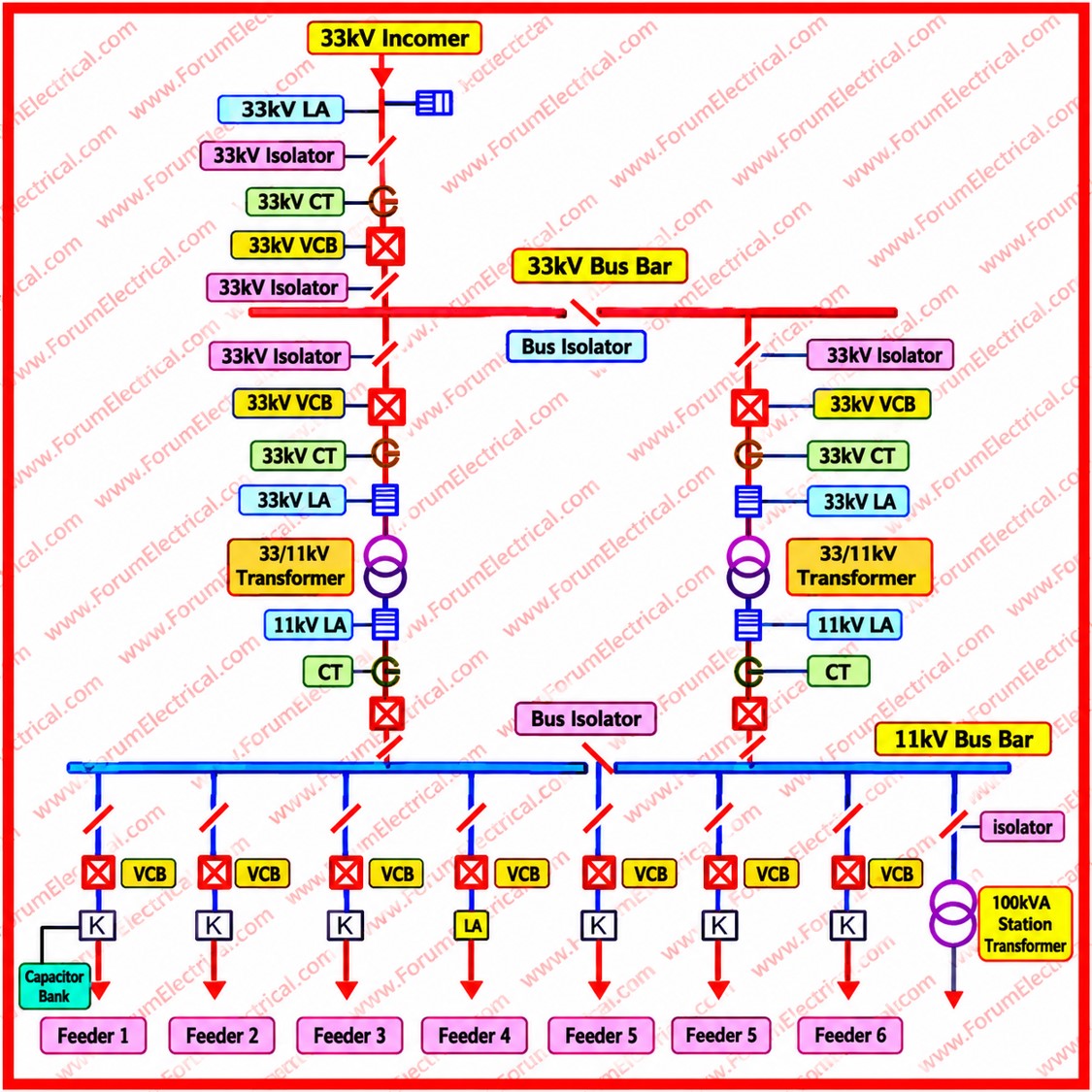
A single line diagram represents a three-phase power system using single line and standard symbols.
It shows how electrical energy moves from the incoming supply to the consumer loads and which devices switch, measure and protect each part of the path.
- Power Flow Fundamentals
- Component-wise Analysis
- 1). 33kV Incoming Supply
- 2). Lightning Arresters (LA)
- 3). Isolators
- 4). Current Transformers (CT)
- 5). Vacuum Circuit Breakers (VCB)
- 6). 33/11kV Power Transformers
- 7). 11kV Busbar with Bus Coupler
- 8). Outgoing Feeders
- 9). Capacitor Bank
- 10). 100kVA Station Transformer
- Protection and Maintenance
- Importance of Understanding SLDs
- Conclusion
The 33kV / 11kV substation SLD considered here covers the full chain:
- 33kV incoming supply,
- Surge protection,
- Isolation,
- Measurement,
- VCB – Vacuum circuit breakers,
- 33/11kV power transformers,
- 11kV busbar with bus coupler,
- Outgoing feeders,
- Capacitor bank and
- 100kVA station transformer.
Power Flow Fundamentals
Power enters at 33kV through the incoming line.
Lightning arresters protect the entry point against surges.
The supply then passes through an isolator and current transformer to a vacuum circuit breaker which energises the 33/11kV power transformer.
The transformer steps the voltage down to 11kV and delivers it to the 11kV busbar.
From the busbar, power is distributed through Feeders 1 to 6 to plant loads or downstream substations.
The capacitor bank and the 100kVA station transformer are also connected to this system which serving power factor correction and auxiliary supply respectively.
Component-wise Analysis
1). 33kV Incoming Supply
The incoming supply is the point of connection with the utility network, usually by overhead line (or) underground cable.
Equipment here must be rated for the maximum system voltage (36kV class) and the prospective short-circuit current.
2). Lightning Arresters (LA)
Lightning arresters, also called surge arresters, limit transient overvoltages caused by lightning strikes and switching operations.
Modern arresters use metal oxide (zinc oxide) blocks.
They present very high impedance at normal voltage and conduct surge current to earth when voltage exceeds a threshold, then recover.
For best protection they are installed at the line entry and as close as practicable to the transformer terminals, so that the residual voltage stays below the equipment insulation withstand level.
3). Isolators
An isolator (or) disconnector is a mechanical switch that gives a visible air gap so that equipment can be safely de-energized for maintenance.
It has no arc-extinguishing capability and must be operated only when the circuit is not carrying current which implies the circuit breaker is already open.
Isolators are often fitted with earthing switches that ground the isolated section.
4). Current Transformers (CT)
Current transformers reduce high primary currents to standardized secondary values commonly 1A (or) 5A for protection relays and metering instruments.
They also electrically isolate these low-voltage circuits from the high-voltage system.
A CT secondary must never be left open while the primary is energized because dangerously high voltage can develop across the open terminals.
5). Vacuum Circuit Breakers (VCB)
The VCB is the main switching and protective device.
Its contacts operate inside a sealed vacuum interrupter where the arc is extinguished at a current zero because of the vacuum very high dielectric strength.
VCBs provide long life, low maintenance and compact size with no arc-quenching oil (or) gas.
A VCB can make, carry and break normal load current and also interrupt fault currents when commanded by protection relays.
6). 33/11kV Power Transformers
The power transformer steps 33kV down to 11kV.
Typical features include oil-immersed construction with natural cooling, an on-load (or) off-circuit tap changer for voltage regulation and a delta-star winding arrangement that provides an 11kV neutral for earthing, provide through a neutral earthing resistor.
Common protections include differential, restricted earth fault, overcurrent, Buchholz, winding and oil temperature devices and pressure relief devices.
7). 11kV Busbar with Bus Coupler
The busbar is the common point that collects power from the transformers and distributes it to feeders.
A bus coupler divides it into two sections.
With the coupler open, each transformer supplies its own section which limits fault levels and confines the effect of a fault.
If one transformer is out of service, closing the coupler lets the remaining transformer supply both sections, improving continuity.
Interlocking prevents unintended paralleling of transformers.
8). Outgoing Feeders
Each of the outgoing feeders is controlled by its own VCB with CTs and relays for overcurrent and earth fault protection.
Individual breakers isolate a faulty circuit without interrupting the others.
9). Capacitor Bank
Inductive loads such as motors and transformers draw reactive power, which lowers the power factor.
A capacitor bank supplies this reactive power locally which reduces current drawn from the source, lowers losses, releases system capacity, improves voltage and avoids utility penalties.
10). 100kVA Station Transformer
The station transformer supplies the substation’s own auxiliary needs at low voltage.
These include the battery charger for the DC supply that powers relays, trip coils and control circuits, together with lighting, cooling fans, tap changer motors, breaker spring charging motors and control panels.
Protection and Maintenance
Coordination: Relay settings across incoming, transformer, bus & feeder levels should be graded for selective tripping.
Earthing: A solid earth grid ensures safe touch and step voltages and effective arrester operation.
Preventive maintenance: Routine checks which include insulation resistance testing, oil analysis, breaker timing, relay testing & thermography.
Safety: Lockout-tagout, earthing before work protect personnel.
Importance of Understanding SLDs
An SLD is the primary reference for engineers and maintenance staff.
It allows rapid fault location by showing which devices lie between the source and the affected load.
It supports planned shutdowns by defining isolation points, helps verify protection coordination and guides safe switching sequences.
Accurate, up-to-date diagrams therefore contribute directly to equipment safety and uninterrupted power supply.
Conclusion
The 33kV / 11kV substation SLD shows a well-structured distribution scheme in which each element has a defined functions:
Arresters guard against surges, isolators and breakers switch and protect, CTs feed relays and meters, transformers change voltage level, the bus coupler adds flexibility, feeders deliver power, the capacitor bank corrects power factor and the station transformer keeps auxiliaries alive.
Understanding the way these components work is important for ensuring safe operation, effective troubleshooting and an uninterrupted supply.

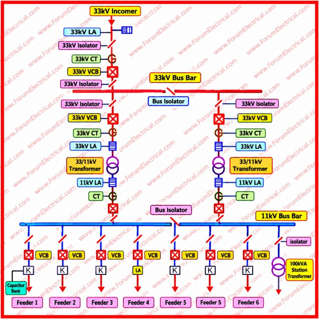
 showing transformers, VCBs, CTs, isolators, busbars, lightning arresters, feeders and protection components.)