
Electrical power is dominant since it is relatively much easier to transmit and distribute more than other forms of energy including mechanical.
It consists of a number of components and procedures that assure an effective and dependable electrical power supply at proper voltage levels.
Now let’s see how electrical power is consumed by the consumers.
What is a Distribution System?
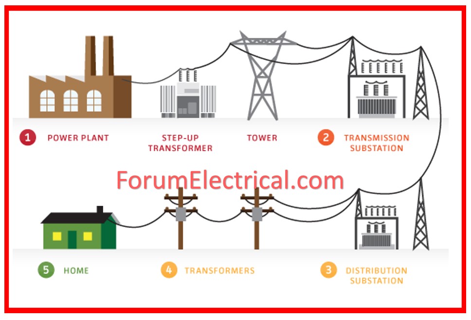
The section of the power system used to supply electric power for consumption locally is referred to as the distribution system.
In general terms, a distribution system is an electricity network station between the substation which it gets from the transmission system and the consumer’s meters.
Components of Distribution System
A typical electrical power distribution system consists of:
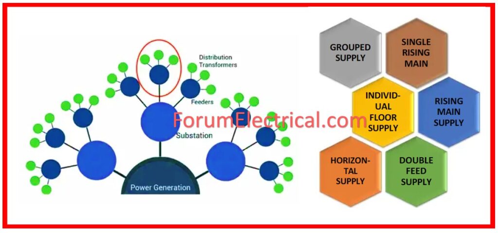
1). Distribution Substation
2). Feeders
3). Distribution Transformers
4). Distributor
5). Service Mains
In addition, a distribution system includes
1). Switches,
2). Protection devices,
3). Measurement equipment, and
4). Other components.
1). Distribution Substation
A distribution substation is the electrical system which distributes power from the transmission system into that of the region.
Distribution substation is the junction, where the transmitted power is received.
It may be situated at the outskirts of a city or a village or in any particular industrial area.
Actually, the power that is transmitted is at a very high voltage which can be such as 400 kV, 800 kV and so on depending on distance of transmission and this is stepped down at the distribution substation.
The voltage reduction occurs as per the necessary levels at the stages of Primary distribution system followed by secondary distribution system.
Primary Distribution System
The primary distribution system is that part of the AC distribution system which functions at voltage higher than general utilization but lower than transmission.
The voltage used for primary distribution depends upon the amount of power to be transferred and the distance of substation required to be fed.
Some commonly adopted primary distribution voltages include 11 kV, 6 kV. 6 kV and 3. 3 kV.
The primary distribution is carried by a 3 phase 3 wire system so as to save cost.
Secondary Distribution System
The secondary distribution system comprises of those voltage ranges at which consumers use the electrical energy.
The secondary distribution uses 440V (3-phase) & 230V (1-phase), 3-phase 4-wire systems in India.
2). Feeders
A feeder is a conductor whereby the distribution substation is connected to the area where power is to be supplied.
The current in a feeder is just the same all along its length as no tappings are taken from it.
In other words, the primary concern in feeder design is its ability to carry a certain amount of current.
3). Distribution Transformers
It is also a step down transformer which has primary and secondary winding and where primary is connected in delta connection and the secondary in star connection (Delta-Star Connection).
Distribution transformer is a three – phase transformer that transforms distribution voltage to the appropriate voltage for the primary and secondary utilities.
It is also referred to as a service transformer.
Distribution transformer output voltage is 440V in the case of 3 phase system and 230V in the case of 1 phase system.
The distribution transformer reduces the voltage to a level where the voltage between a phase and the neutral = 220V While the voltage between phase to phase = 415V.
While in the US and some other countries the phase-to-phase voltage is 240 volts, and the single phase is 120 volts.
Normal distribution transformers are typically those with a rating of below 200 KVA.
These transformers have to operate continuously to meet the power demand; therefore, they need to have low iron losses.
Normally they do not work at full capacity; therefore, they are designed to be more efficient at a small load.
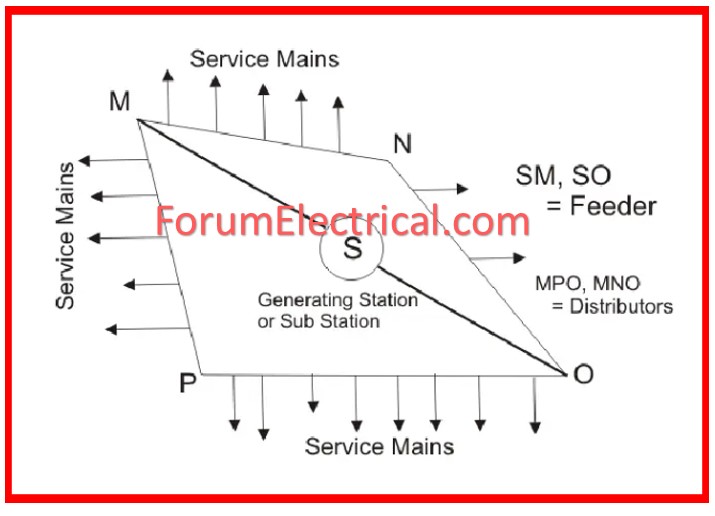
4). Distributor
A distributor is a conductor from which tapings are given for supplying the consumer.
Since the taping is at different locations in a distributor the current is not the same throughout the length of the distributor.
The main design factor of a distributor is the voltage drop along its length because voltage fluctuations are limited by law to ± 6 % of rated voltage at the consumer end.
Since there are multiple tappings the amount of current flowing through the distribution conductors is not the same.
However, the voltage drop in distribution conductors should be maintained to a minimum.
5). Service Mains
It is a small cable which is used to connect the distributor with the consumer’s meter.
Classification of Distribution System
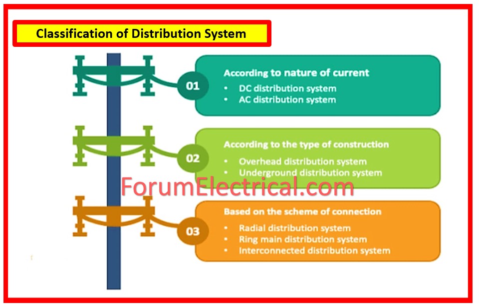
Based on Current
DC Distribution System
- The transmitted AC power can be rectified at the distribution substation with the help of power electronic converters and can be supplied as per the consumer’s demand.
DC distribution is of two types:
- Unipolar DC Distribution system also known as 2-wire DC distribution system.
- Bipolar DC Distribution system also known as 3-wire DC distribution system.
AC Distribution System
- AC power distribution is the most popular type of system of power distribution as most of the loads, commercial or residential use AC power.
- As a result, the power transmitted at high voltage is stepped down to appropriate voltage level and distributed to the consumers at distribution substation and then disbursed.
There are two main types of AC distribution systems that are commonly used today namely the
- Single phase systems and
- Three phase systems.
Regarding the AC power distribution, there are many methods.
- Single-phase, 2-wire system
- Single-phase, 3-wire system
- Two-phase, 3-wire system
- Two-phase, 4-wire system
- Three-phase, 3-wire system
- Three-phase, 4-wire system
Based on Construction Type
Overhead Distribution System
- Overhead distribution system is the oldest and the most widely used method of supplying power.
- In this, the power is supplied through overhead wires fixed to the road side light poles for its transmission.
- These are the poles or similar structures on which transformers and other needed equipment for mounting are placed at.
- This system is economical and requires less managerial overhead compared to other systems.
- However, being in the outer atmosphere, it is sensitive to different kinds of weather occurrences.
Underground Distribution System
- Underground distribution system has gained popularity due to the modern advancement in electrical power distribution.
- It is not like other systems which require poles and supporting structures and it has no overhead hanging wires.
- It is, however, more expensive than the overhead version, and challenging to manage & control.
Based on Connection Type
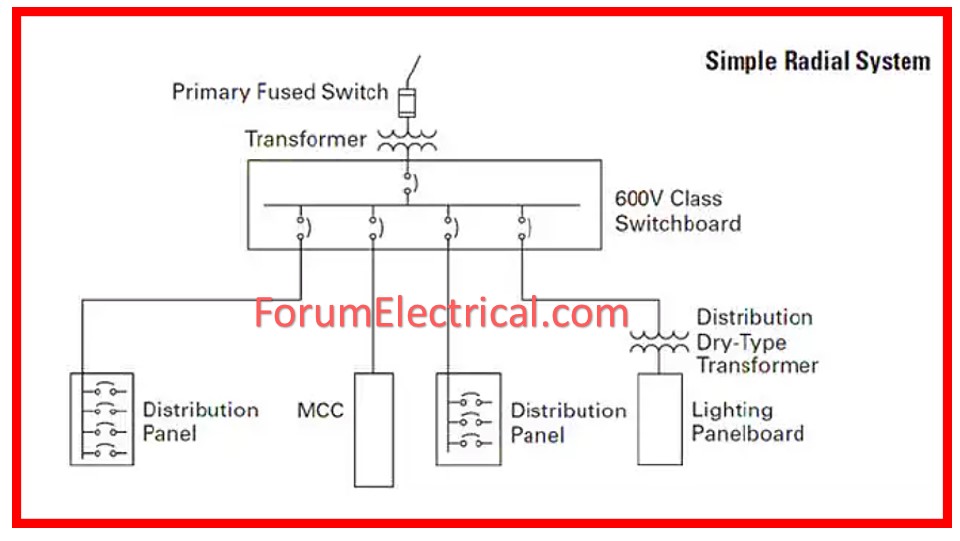
Radial System
- Radial distribution electric power distribution system is used where the distribution substation is centrally situated with reference to the consumers from where the feeders emanate and spread in all directions.
- As for the flow of power, it mainly operates in radial distribution in one direction.
- It is cheap in terms of implementation but one of the major disadvantages is that if there is a problem with a feeder, all the consumers that are connected to it are disconnected from the power supply.
Ring Main System
- The ring main distribution system therefore consists of feeders which are in a closed loop or a ring from which are derived distributors.
- Thus, there is no terminating end in the feeders through which this system makes a continuous loop network.
- The advantage of this system is that there are duplicate feeders supplying each distribution transformer.
- It helps in maintaining the supply voltage by providing an additional path or in the case of damage of any section along the feeder.
Inter-Connected System
- If a ring main feeder is supplied by two or more sub stations or generating stations then it is known as an interconnected distribution system.
- This system makes a reliable backup in case of transmission failure.
- Also, any area supplied by one of the generating stations during peak loading hour is able to be supplied in a similar way by the other generating station or substation to cater for power demand from increased load.
Parallel Feeder System
- The parallel feeder distribution system was therefore developed to eliminate the shortcoming of the radial distribution system.
- Here instead of a feeder, Parallel feeders are used for supply of power.
- This system is, however, more costly than the radial system of distribution, though it is more reliable than this system.
Requirements of a Distribution System
Some of the requirements of a good distribution system are the following:
Voltage Drop
In consumer’s terminals, the voltage should be as low as possible. The permissible variation of voltage as per the statute is ± 6 % for India with regard to the rated voltage at consumer’s terminals.
Availability of Power on Demand
The electric power should be supplied to the consumers in whichever quantity they may need at any given time.
Reliability
The modern industry is almost reliant on electric power for the performance of its activities. This means we need to seek service that is dependable as often as achievable.


