
Pre-commissioning testing is an important step before turning on any electrical equipment (or) system.
These tests ensure that the equipment was properly installed, is free of manufacturing or installation faults, and satisfies all safety and performance requirements.
Proper pre-commissioning ensures long-term reliability, reduces the chance of failure, and helps fulfill industry standards such as IEC, IEEE, and IS.
The following is a thorough list of essential pre-commissioning tests for electrical systems and equipment, including
- Transformers,
- Switchgear,
- Motors,
- Cables, and
- Protective systems.
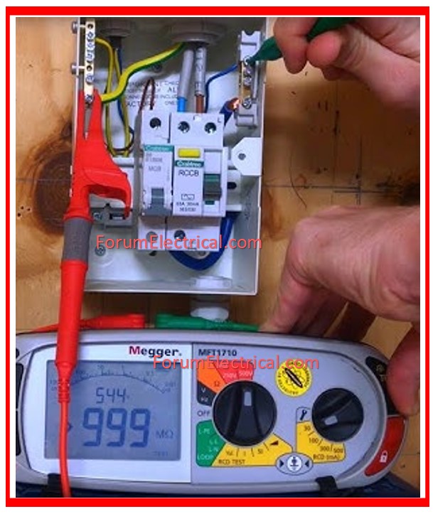
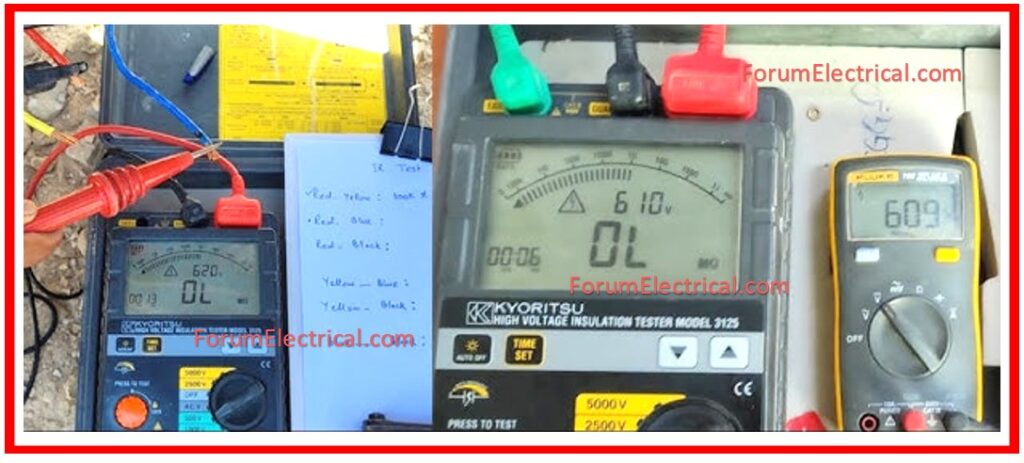
Insulation Resistance Test
For a brief period of time measure the insulation resistance (IR) of electrical equipment from
- Phase to Phase and
- Phase to Ground.
Determine the voltage and minimum permissible values.
| Equipment Voltage Rating | Recommended Tests Voltage |
| 100 – 250 | 500 |
| 251 – 600 | 1000 |
| 601 – 5000 | 2500 |
| Over 5000 | 5000 |
Insulation resistance values less than the manufacturer’s minimum (or) rated voltage plus 1kV in megohms should be analyzed.
Over potential or high potential tests should not be conducted unless insulation resistance (IR) levels are equal to (or) greater than the indicated minimum values.
High Potential Test
Direct Current (DC)
A DC high potential test is one that requires the amount of applied direct voltage is controlled.
The measured current is constantly monitored for abnormalities with a purpose of terminating the test prior to breakdown occurs.
To perform a polarization index test on large rotating equipment, start with one-third of the suggested maximum voltage from the table and keep it constant for 10 minutes.
The polarization index is obtained by dividing 1-minute resistance value by 10-minute resistance value.
The index value should be two or more; numbers less than this ought to be explored.
After the initial ten-minute test, increase the D. C. test voltage in ten uniform steps of one minute each, up to maximum allowed D. C. value.
For high potential cable testing, the direct current (DC) test voltage should be applied in four one-minute stages, each of which should be approximately equal to cable’s rated RMS voltage. The final test voltage, on the other hand, should be maintained for fifteen minutes.
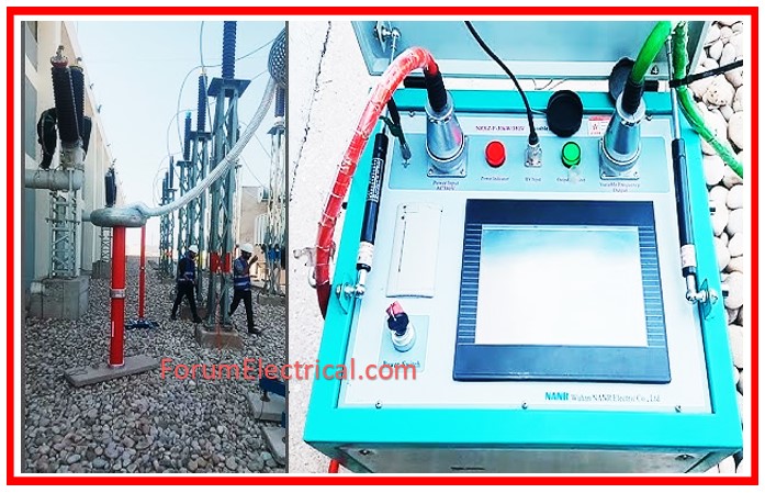
Alternating Current (AC)
There is a high potential for testing
- phase to ground &
- phase to phase.
The potential application will be for a period of one minute. A voltage test must be performed in accordance with the instructions provided by the manufacturer.
Increase the voltage at a rate of 1 kV per second till the maximum permissible test voltage is achieved.
| Equipment Rated KV | Test Voltage KV | |
| Alternating Current (AC) | Direct Current (DC) | |
| 2.5 | 6 | 10 |
| 5 | 14 | 24 |
| 15 | 27 | 46 |
| 35 | 60 | 102 |
The AC high potential test results are assessed on a go, no-go basis by gradually raising the test voltage to the necessary value of the final test voltage and sustaining it for 1 minute.
Low Voltage Cable Test
Conduct DC High Potential Testing on important wires after installation.
Test each cable in relation to the ground and nearby cables.
The test value will be verified with the proponent.
The DC test voltage cannot exceed 1.4 x (2 x rated voltage + 1000).
Switchgear & Metal Enclosed Bus Test
For one minute, conduct AC high potential tests on every bus segment, including phase to phase & phase to ground. The maximum test voltage needs to be as mentioned above.
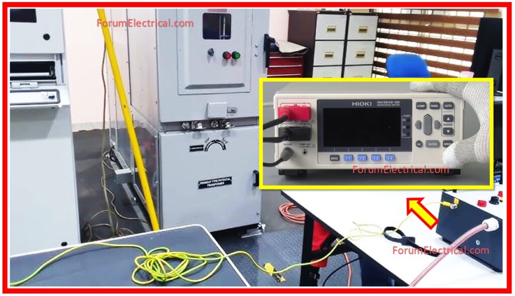
Contact Resistance Test
Take measurements and make a record of the contact resistance of each phase of the line to load, starting with the
- Bus,
- Breakers, and
- Contactors.
Resistance levels greater than 200 microohms and variations greater than +/- 20% should be studied for equipment rated at 600A or above.
The contact resistance is determined with the circuit breaker (or) contactor in closed state.
The contactor should be closed & locked, not held tight with manual pressure.
Thermo-Vision Inspection Test
Electrical equipment that is safely accessible and visible, such as
- Outside bus connections,
- Isolation switches,
- Circuit breaker terminations, and
- Transformers,
should be checked for temperature deviations using Thermo-vision.
New Insulating Oil Testing
The following table contains the Dielectric Fluid Specifications for the new insulating Oil as supplied by the supplier.
It should be noted that the mentioned values are either the lowest (or) highest recommended values.
It is important to conduct a test on the oil before starting the process of filling the equipment with oil.
The results of the test, as well as the voltage at which the equipment operates, will determine whether or not the oil needs to be treated before it is put into the equipment.
| Test | Limit Value | Test Results |
| Dielectric strength (minimum) (kV) | 30 | |
| Power Factor 250 – % maximum 1000 – % maximum | 0.050-30 | |
| Interfacial Tension (minimum) (mN/M) | 40 | |
| ASTM Units (maximum) | 0.5 | |
| Visual Testing | Bright & Clear | |
| Acid Number (mg KOH/g), (maximum) | 0.03 | |
| Water Content (ppm) (maximum) | 35 |
Standards in Pre-Commissioning Testing
- IS 3043:1987
- IEEE Std 81-2012
Conclusion
Pre-commissioning testing is more than simply a mandatory requirement; it’s an important precaution that ensures all electrical equipment & systems work as intended from the initial installation.
Each test improves system dependability, staff safety, & asset longevity.


