
What is a Ground Fault?
A ground fault is an any short circuit that results in an undesired connection between a ground and an energized ungrounded phase conductor and ground.
- What is a Ground Fault?
- What is Ground Fault Testing?
- What types of problems have been identified?
- What is the Reason for Ground Fault Testing?
- What is done during Ground Fault Testing?
- What Procedures are undertaken when testing the Ground Fault System?
- Ground Fault testing of the Current Transformer
Faults occurring between the phase and earth are deemed ground faults, and these often occur with power distribution systems.

They are as a result of insulation break down (or) accidental earthing of an ungrounded phase conductor coming into contact with the ground.
Equipment that can be accidentally grounded includes a small animal touching an ungrounded phase conductor and the equipment enclosure.
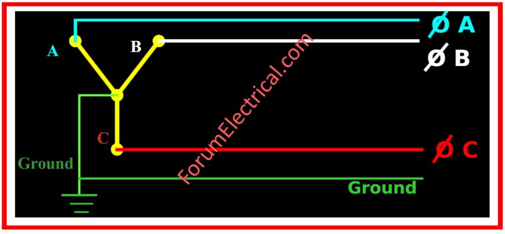
They ensure that the current going out through any one phase is returning either through the other phase or the neutral wire.
Following situations depict the occurrences of the ground fault:
- If current is going out on phase but is coming back on the ground path.
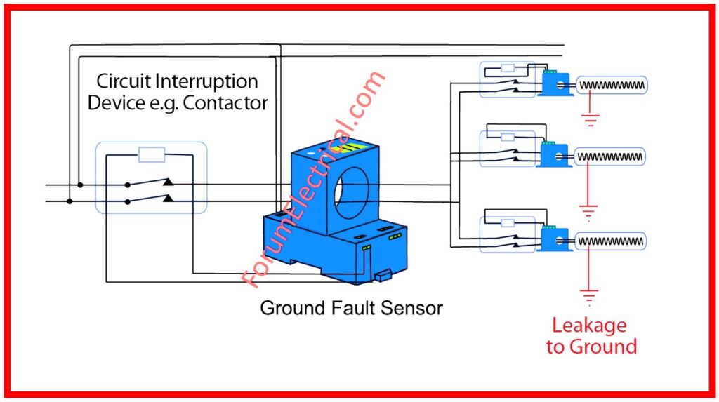
All systems with ground fault protection include:
Current transformers to generate signal current for ground fault current (GFC)
Relay or a logic box that helps with defining the tripping current value and time.
An operating mechanism to open the breaker or switch a circuit breaker open or a switch opens to cause a discontinuance in the stream of electrical energy.
Some systems have a monitor panel that shows status of the system in question coupled with a test panel that enables the creation of a ground fault signal for the testing of the breaker in question.
What is Ground Fault Testing?
Ground Fault Testing is a method that is used to find out any stray current out of the electrical system and towards the grounding system.
It entails looking for abnormalities that are usually known as faults that enable current to flow from the desired circuit path to the ground which is risky for instances like
- Electric shocks and
- Accidental fires.
The methods used in ground fault testing may involve
- Measuring the insulation resistance,
- Ground Fault Circuit Interrupters (GFCIs), or
- Specific ground fault detection equipment
that will help locate then remove the fault.
This makes the electrical system safe and dependable since ground faults could pose a serious threat through electric shocks.
What types of problems have been identified?
- Neutral grounded downstream may also cause a disturbance to the ground fault or lead to tripping failure.
- Some of the problems that can arise from wrong current sensor mounting or polarity could include false tripping.
- Lack of control power or connections results in the inability of protection devices to trip.
- Their tripping characteristic is also influenced by the fact that failure to trip within the manufacturer’s tolerance is likely to offer inadequate protection.
What is the Reason for Ground Fault Testing?
The existing code from the US, known as the National Electrical Code (NEC), Art. 230.95(C) requires that the ground-fault protection system must generate the performance test once installed on site for the first time, and the test should be carried out as per the instructions provided with the equipment.
National Electric Code for Fault protection has it that ground fault relays were designed to protect equipment from low magnitude effects that relate to conduction of electricity between the equipment and the conducting body.
There is no guarantee for the gear protection concerning the influences of larger magnitude ground faults.
Measures against the higher magnitude ground faults are based on protection assets as
- Fuses and
- Circuit breakers.
What is done during Ground Fault Testing?
Ground fault testing includes:
Visual and Mechanical Inspection
Nameplate data of the equipment should be compared with their specifications as well as drawings.
Check for component damage, polarity, and conductor routing errors:
- Ensure the ground connection is made prior to the neutral disconnect link and before the ground fault sensor, if included.
- Check that the neutral sensors are associated with accurate polarity in both the primary as well as the secondary.
- It should be ensured that all phase conductors as well as the neutral pass through the sensor in the same direction in the case of zero sequence systems.
- Ensure that the grounding conductor does not go through the 0 sequence sensors.
- Check that the grounded conductor is stated grounded.
Use one of these procedures to check bolted electrical connections for the high resistance:
- Employment of low-resistance ohmmeter as required.
- Ensure that reachable bolted electrical connections are stiff by use of calibrated torque wrench method as recommended by the manufacturers.
- Perform thermographic survey.
- Ensure that all the functions of the self-test panel are working as required.
- Ensure that the control power transformer that has been established can adequately handle the system.
- Select the time delay and the pickup with the settings stated in the owner’s specifications.
Electrical Tests
Bolted connection areas should be checked with a low-resistance ohmmeter, if appropriate, to carry out resistance measurements through bolted connections.
Check the system neutral-to-ground insulation resistance with the neutral disconnect link open.
Testing Neutral Insulation Resistance
It is necessary to test the insulation resistance as problems are created by the grounded neutrals disadvantage of the sensing device.
The first of these involves the application of some temporary measure by which the neutral disconnect link is taken out for a short time.
Disconnect links should be changed after the test to ensure it has no sort of connection with the rest of the circuit or system.
Carry out insulation resistance test on total control wiring in association with ground.
It is recommended that employed potential should be; 500 VDC when the cable is 300V rated and 1000 VDC when the cable is 600V rated. Total time for the tests shall be one minute.
For units that cannot tolerate the applied voltage or units containing solid state components, the practice should be done according to manufacturer’s advice.
After this, make measures of the voltage between the neutral and the ground. The value should be set to a minimum of 1 megaohm.
In the event that the neutral is ascertained to be less than 1 megaohm, correct the situation before deployment of the equipment.
Typically the use of an ohmmeter is made to take this reading.
Care should be taken if an insulation resistance test set is used.
Touching the downside of the circuit which is connected with the gear, may result in damaging the parts with high voltage on the neutral.
At the end of testing, change the neutral disconnect link.
Primary Injection Testing
This includes feeding the primary current into gear’s neutral and phase conductors in order to correspond with the movement of ground-fault current under varying circumstances.
This will prove that transformers are connected and properly secured as well as being warranted that the switch or breaker for not tripping under operating conditions.
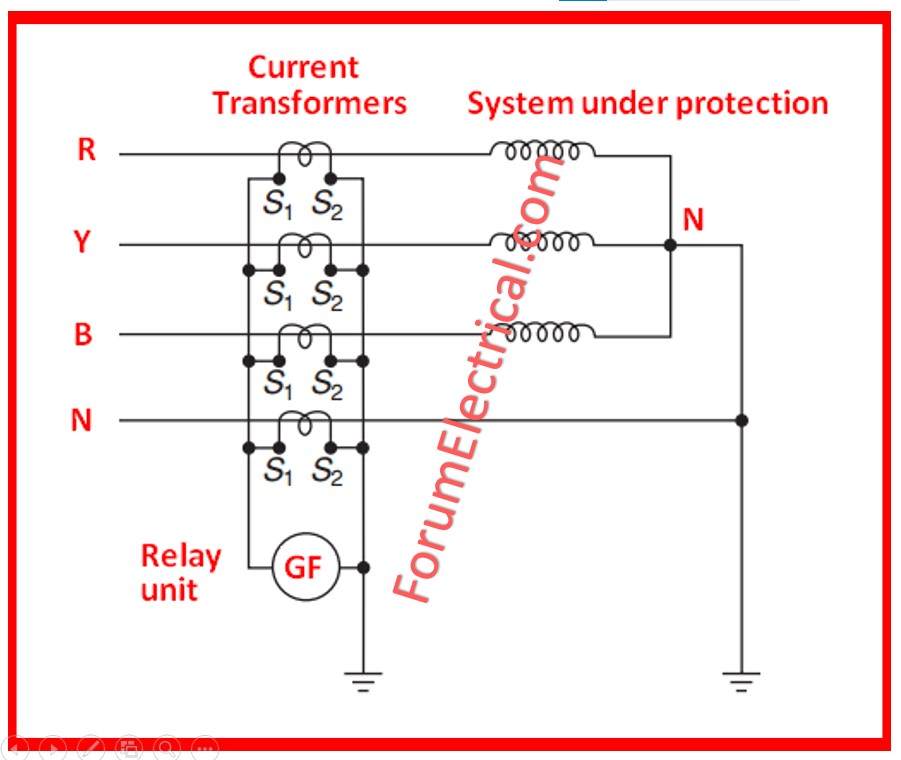
Two of the commonly utilized ground fault systems are
- Residual sensing method and
- Zero-sequence sensing method.
Testing Reduced Control Voltage Tripping
Control voltage is necessary for almost all ground fault testing methods to function, and control power transformers are used in all of the techniques to provide the control voltage.
This is beneficial as the ground-fault system is an individual system that does not need an additional source to work.
The shortcoming is that the control power can be decreased in the course of a ground fault; however, the gear must be capable of running at reduced voltage to clear the fault.
What Procedures are undertaken when testing the Ground Fault System?
There are two tests for assessing the value of the ground fault protection systems either by using the
- Simulated Fault Current Method &
- High-Current Primary Injection Method.
These methods can be used on a ground-fault relay system but to test a system with integrated ground-fault trip circuit breakers, a high current primary injection can be employed.
If the high current test does not generate the required tripping, check the control power at the fuses, transformers, as well as at the relay.
Simulated Fault Current Method
In a correct sensor, an imitation of a fault current is obtained with the help of a coil round a window type sensor or with the help of a distinct test winding in the sensor.
A secondary current is developed in the sensor when the monitor panel passes a small current through the test winding, and the relay acts corresponding to it as though the primary current of 1600A has been passed.
Using an similar method that may be used on any window type sensor that includes a ground fault relay, variety of turns of wire are wound round the sensor core such as twenty turns of #14 wire.
A current is passed through the wire to mimic the ground-fault current, which is roughly 125% of the relay’s pickup setting divided by the turn.
Using simulated fault current allows providing explanation of the relay, sensor and shunt trip’s work and adequacy of the control power supply.
We also need to verify information by checking the GFP system that the neutral ground points are correctly positioned with respect to sensors, that the polarity of individual sensors is correct if many are connected in parallel, and that all conductors passing through a window run in the same direction.
The need to add simulated fault current testing with sufficient inspection can be well understood when one realizes that, out of the first 5 items in the Checklist, there are problems that cannot in any way be diagnosed through a simulated fault current testing only.
High-Current Primary Injection Method
The high current injection test method might be applied in testing ground fault protection systems that have built-in ground fault trips of circuit breakers or ground fault relays.
It serves as the like of fault current simulation along with inspection in the case of relays.
Last method to perform the system test for integral ground fault protection in circuit breaker is the high current injection test only.
TAK-TS2 (The subsequent solid-state overcurrent trip devices are tested in the field using this portable instrument.) that is used collectively with AKR-SST/ECS (Overcurrent Trip Device) trips can be used to ascertain the internal electronics of these breakers.
Essential characteristics of high current testing of ground fault protective systems involve feeding full scale current into the equipment phase and neutral conductors minimizing normal operating conditions of ground fault current.
The testing gear required includes the high current supply which should be capable of supplying up to thousand amperes or even more at 2. 5V.
Thus, ground fault current pickup settings on the relays and breakers or switches shall be limited less than the current required to trip, for instance 400 or, 300A or even lower.
Testing experts may need a current source capable of providing 2,000 amps or more in order to conduct tests at the maximum ground fault protection setting.
Link the current supply and jumpers according to the points described in the tables beside the diagrams.
The protection should be supplied for the three wires and the four wire gear derived from a solidly grounded four-wire source.
To keep the overcurrent device working, the ground fault current return path to the neutral must have low resistance.
Test Values
Bolted connection resistances should be matched to values of the same connection.
The Millivolt drop values or Micro-ohm should not exceed the high limit set under normal range as provided for by the manufacturer’s literature.
When specific product values are out of line with similar relations and manufacturer’s information is not available, investigate disparities more than fifty percent of the lower value.
The insulation of the System to neutral should be at least 1.0 megaohm.
Control-wiring insulation resistance shall be a minimum of 2.0 megaohms.
Relay timing should closely align to the manufacturer’s recommendations; however, the timing should not be less than one second at three thousand amperes.
Ground Fault testing of the Current Transformer
The system performance testing as required by NEC 230 is sometimes necessary.
It is a fact that 95(C) is usually sought to be complied with by a third party electrical testing company and not the installing contractor or the owner.
Any testing that needs to be done should be conducted before the energizing of the device is done.
It is important to note that while testing ground-fault systems it is necessary that both the line and the load connected to the device being tested has to be disconnected.
The only electrical test that is possible on energized devices is with the help of a secondary injection test set.
- Application of a secondary injection test set will check the electronics of the relay or trip unit but does not guarantee the correct installation of CTs and wiring.
- The utilization of the test-trip button will test the circuit inside the relay or trip unit, however it doesn’t guarantee the CT installation and the wiring are correct. This does not meet the requirement of performance testing as defined in the NEC 230. 95(C).
- A direct test checks the relay or trip unit and its control power as well as the wire and the external CT using a primary injection test set.
- Primary injection tests commonly include both the trip and non-trip tests whose aim is to prove the polarity of the CTs or sensors and the wiring of the system.
- When a system requiring control power is tested, a reduced voltage test is also made to ensure that the system will also trip, although the supply power has lost a phase.
- Since there are different types of ground-fault systems, this wire draws a certain level of special focus.
- Some have minimum sizes of conductors, shield conductors and require that the conductors have to be twisted together before the CT connection.
- Certainly, the acknowledgment that the polarity of the CT is correct is quite hard-most of the time because of the position of the CT.
- Since it is common that the control power for the ground-fault system is a tap conductor originating or deriving from the line side of the overcurrent device, this may therefore be a type of disconnect device fused with a fuse block.
- This is the power for the ground-fault relay and should be ascertained to be in the ‘on’ or ‘energized’ position.
- Maintenance field operatives have physically accessed the control cabinets of several operational systems and discovered that the switches were on the off position.
- At that point, it becomes very difficult to determine if it has never been switched on before or if it was switched off at some point to conceal nuisance tripping or some other trouble in the electrical power system.
- Hence if the control power is not provided to an external system, there will be no ground-fault protection.
- If a ground-fault system is intentionally turned off and somebody obtains an injury as a result.
- Since the third-party ground-fault protection performance testing is frequently carried out before conductors are connected to the CT, the CT should be closely inspected after conductors have been pulled through the CT.
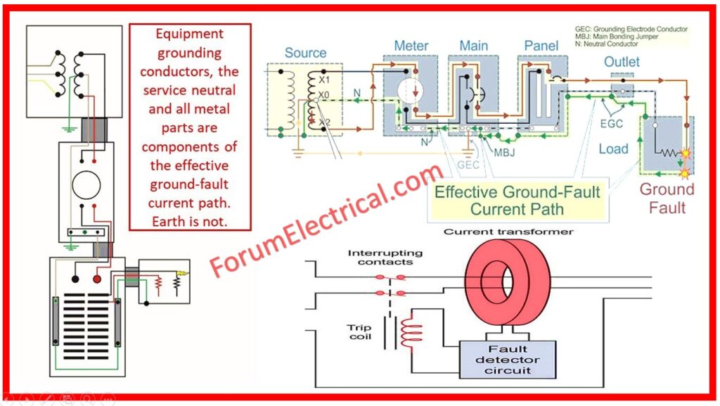
- Confirm that the grounding system is properly done. The grounding system served as the return path of a system fault.
- Check out the position of each neutral conductor at each point in the system to ensure that it is not bonded downstream.
- This is often confirmed if the ground fault performance test is completed but typically is conducted when the electrical distribution system is still under construction; hence, a close attention should be paid so that the systems are correctly designed to work appropriately.
- Grounding of the neutral conductor quite often keeps the ground-fault protection system non-operational during the system ground fault condition.


