")
- What is a Pressure Test in Electrical?
- What is HV Pressure Testing?
- Transformer Tests –11/0.433 kV 250 kVA
- HV Pressure Tests (132kV Equipment)
- Supervisory Interface Test
- 11 kV VT Tests
- 11kV CT Tests
- 11kV Primary Injection Test
- 11kV Secondary Injection Test
- 11kV Switchgear Contact Resistance Checks
- 11kV Switchgear Operational Test
- Battery and Charger Test
- Earthing Test
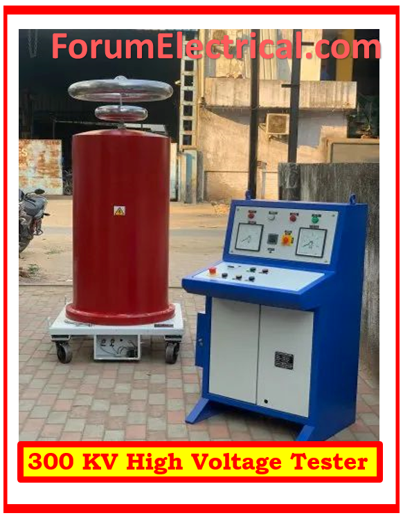
What is a Pressure Test in Electrical?
A pressure test for electrical systems, also known as a pressure or dielectric withstand test, is applying a high voltage (HV) to an electrical component (or) system to ensure insulation integrity.
This test ensures that the insulation can sustain working conditions without breaking down, hence eliminating electrical shorts and failures.
It is a key safety precaution used in manufacture and maintenance to discover any flaws in
- Cables,
- Transformers,
- Switchgear, &
- Other electrical equipment,
assuring that they satisfy regulatory standards and are safe to use.
What is HV Pressure Testing?
High voltage cable testing is referred to as pressure testing.
Our professionals perform very low frequency (VLF) testing or 5–60 kV DC testing on HV cables in accordance with the DNO (Distribution Network Operators) specification.
High voltage cable needs to be pressure tested in accordance with the right specifications before being used as a resource for a DNO or iDNO (Independent Distribution Network Operator).
Transformer Tests –11/0.433 kV 250 kVA
The layout of the Works Site Test Report is followed when conducting these tests. The following tests are carried out:
- Winding Insulation Level
- Ratio Test
- Vector Group Test
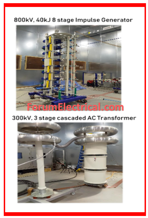
HV Pressure Tests (132kV Equipment)
These tests will be conducted in compliance with the Work Site Test Reports.
The amplitude & duration of the test voltage are shown in the table below. During the tests, there will be a possibility for testing the VT calibration.
| Equipment | Test Voltage (KV) | Duration |
| 132 KV GIS | 115 | 10 min |
| 11 KV | 24 | 1 min |
Supervisory Interface Test
The tests will include triggering alarms at the source and ensuring appropriate logic signals are being received at the TTB cabinet.
Supply a 50V DC voltage to (TTB) cabinet terminals & ensure the relevant circuit breakers (or) tap changer order is received and performed.
11 kV VT Tests
The testing will include:
- Insulation Test and
- Flick Test.
The polarity of VT shall be verified by performing the flick test.
11kV CT Tests
The testing will include:
- Insulation Test
- Flick Test
- Resistance Test
- Saturation Test
When more than one CT is in every phase of a circuit, practical testing will be carried out to ensure the CTs are positioned correctly so that the arranged overlap of regions of protection is correct.
This can be accomplished using one of two methods:
- A Visual Inspection or
- A Continuity Test
Flick tests will be performed on all CTs in a group to ensure that they are all connected to the protection in same polarity.
These tests will also be performed on CTs placed in transformer bushings. The flick test results must be compared to the expected values from the schematic diagrams.
All CTs will have their
- DC secondary loop resistance and
- Individual secondary winding resistances measured.
The saturation tests will be carried out to show that there are no shorted turns linked with the CT & to establish knee point voltage of the CT’s.
The magnetization curve for each CT will be drawn (or) superimposed on factory curves to ensure that the right CT is installed.
11kV Primary Injection Test
The following tests will be conducted:
- Polarity and CT Ratio Test
- Conduct relay operation Test
- Unit Protection Operation & Stability Test
Primary current must be conducted through each CT to determine its ratio and polarity in comparison to other CTs in its group.
All relays & instruments will be shown to be wired in the proper phases.
All current “test terminals” will be verified for proper phasing and CT shorting.
Switches will be tested, and any withdrawable relays’ shorting contacts should be verified.
Inverse time relays will be programmed to “creep” on the minimal setting.
Transformer-biased differential protection.
The group of CTs should be tested for ratio & polarity, & the differential relay tested for phase-phase & phase-earth fault injection.
Transformers have restricted earth fault protection.
Spill currents will be measured to establish the CT groups’ ratio, polarity, and stability.
11kV Secondary Injection Test
The secondary injection tests are scheduled to be performed to ensure that
- Relays,
- Transducers, and
- Meters
are operational and measuring properly.
Secondary injection tests will include ‘A.C.’ injection into relay coils to ensure that the relay calibration is proper.
A record of relay type, serial number, & setting range must be documented.
The secondary current injection will start at the point where the main injection checks were performed on the CTs.
For inverse time relays, the minimum starting current at which the relay closes its contacts with a maximum time dial setting must be documented.
The disk resetting time must be documented, as well as operation time for a current injection of twice, five times, and 10 times the setting current.
These results must be based on the relay’s service configuration (or nominal value if the service is unknown). The results must be compared to the relay curve provided by the manufacturer. The time setting multiplier properties will also be tested at two points (setting point plus another point).
All relays with mechanical flags should work shortly before the contacts are made, & the flag mechanism must not interfere with relay’s operation.
Calibration of all instruments & transducers will be performed at scale and full scale using current (or) voltage injection as needed.
11kV Switchgear Contact Resistance Checks
The contact resistance of all principal contacts will be tested using
- Current injection &
- Voltage drop measurement.
11kV Switchgear Operational Test
The following tests will be performed:
- Local and remote operation of all circuit breakers
- Local & remote indications of above
- Electrical interlocks
- Gas monitoring sequence tests
- Alarm Sequence Tests.
- Tripping tests, including Arc Fault Tripping Scheme.
Sequence tests will be performed to ensure that all electrical circuits function properly.
The control circuits will be tested by manually operating all close-trip switches at all positions, as well as all circuit breakers & other devices.
The operation of every protection circuits will be demonstrated to be consistent with the protective gear.
The tests will be carried out by manually creating each main relay contact and monitoring
- Circuit Breaker tripping,
- Auxiliary relay operation,
- Lock-out relay operation, and
- Any other occurrences.
Tripping triggered by each relay in a protection system will be tested using the appropriate trip link in & out to ensure that it is properly connected and tagged.
The annunciator circuits, which include an alarm buzzer or bell, lights, and any other means of notifying staff, shall be verified to be appropriate.
The alarm circuit will be tested by running each alarm initiating relay contact at its source, if possible, or by simulation.
The operation of each
- Circuit Breaker Disconnect Switch and
- Earthing Switch
will be verified as free or locked based on the interlock state displayed.
Battery and Charger Test
During the pre-commissioning stage, members of the commissioning team will have assembled, tested, and put the batteries and chargers into service.
However, additional tests are now performed, and others are repeated throughout the acceptance testing phase to be observed by the consumer. These tests will be conducted out in compliance with the manufacturer’s approved testing protocols, which will include battery discharge tests.
Earthing Test
The erection personnel will have initially performed earthing tests, but they shall be repeated at the acceptance testing stage, which can be witnessed by the consumer.


, which is used to ensure the insulation integrity of electrical systems. This vital safety test uses high voltage to detect any faults, assuring equipment reliability and conformity with industry standards.)