
A programmable logic controller (PLC) is an industrial control system that monitors field conditions, executes programmed logic and commands outputs.
A simple control path is
Sensor → Digital Input → PLC Logic → Digital Output → Actuator
with feedback added when confirmation is required.
This architecture is common in motor control, pumping, packaging, material handling, HVAC and many other automation systems.
The PLC receives electrical information from field devices and processes it according to its configured program and task structure and generates output commands.
Exact scan behavior and I/O updating depend on the PLC manufacturer, CPU model, firmware, configuration and I/O architecture.
Basic Control Loop
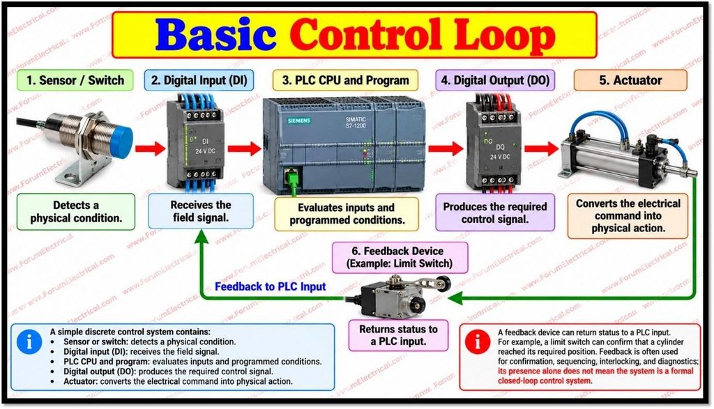
A simple discrete control system contains:
- Sensor (or) Switch: detects a physical condition.
- Digital input (DI): receives the field signal.
- PLC CPU and program: analyses inputs & programmed conditions.
- Digital output (DO): generates/produces the required (or) needed control signal.
- Actuator: converts each electrical command into a physical action.
A feedback device can return status to a PLC input.
For Example:
A limit switch can confirm that a cylinder reached its required position.
Feedback is often used for confirmation, sequencing, interlocking and diagnostics and its presence alone does not mean the system is a formal closed-loop control system.
PLC Scan and I/O Updating
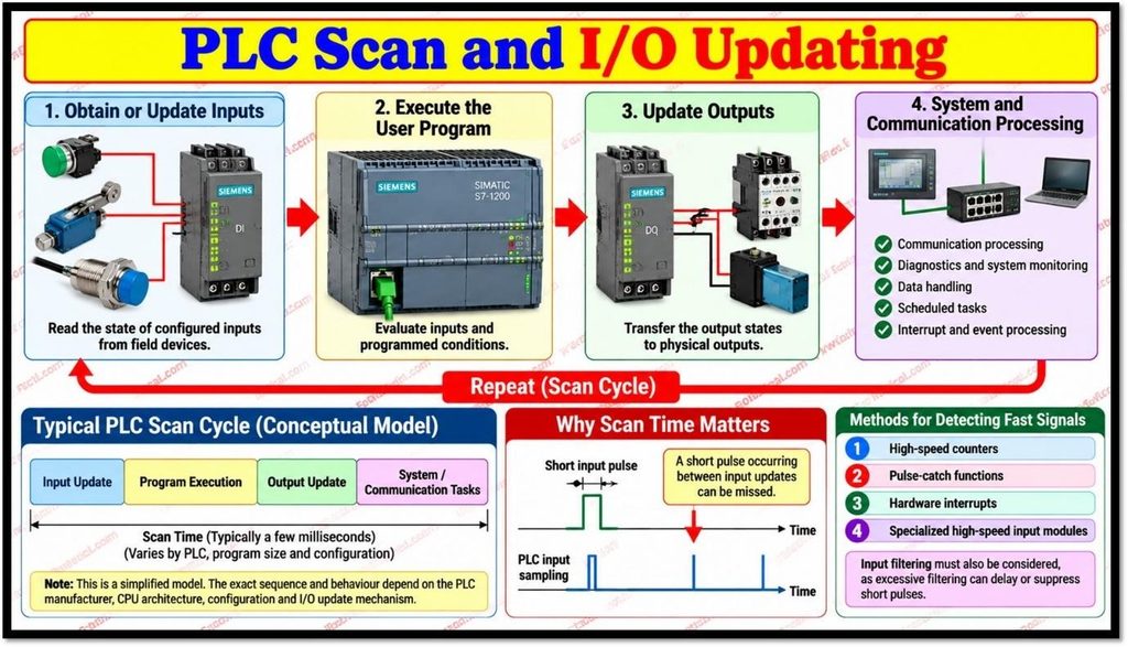
Many PLCs execute user logic cyclically.
A simplified model is:
Obtain (or) update inputs → execute the user program → update outputs → perform system and communication processing → repeat.
This is a conceptual model rather than a universal fixed sequence.
Modern PLCs may also support process-image partitions, direct peripheral access, scheduled tasks and hardware or event interrupts.
For Example:
Siemens S7-1200 documentation describes process image operation in which configured inputs are read into an input image and the program executes using those values and outputs are transferred to physical outputs.
It also describes interrupt-driven processing.
Scan time is important because an ordinary cyclic input can miss a pulse that occurs entirely between input updates.
- High-speed counters,
- Pulse-catch functions,
- Interrupts (or) specialized input modules
can be used for fast signals.
Input filtering should also be considered because excessive filtering can delay (or) suppress short pulses.
Sensors, Digital Inputs and PNP/NPN
Digital sensors normally represent 2 states such as ON/OFF (or) 1/0.
Examples include
- Limit switches,
- Proximity sensors,
- Photoelectric sensors,
- Pressure switches and
- Auxiliary contacts.
Common industrial control voltages include 24 V DC while suitable input modules may also accept 120 V AC (or) 230 V AC.
The actual voltage should match the module rating.
Input modules may provide isolation, filtering, diagnostics (or) surge protection but these features are module-dependent.
For DC discrete I/O, sourcing and sinking compatibility is essential.
A PNP sensor typically sources current toward a compatible sinking PLC input while an NPN sensor typically sinks current from a compatible sourcing PLC input.
Manufacturer wiring diagrams should always be followed.
NO, NC and Safety
Normally open (NO) and normally closed (NC) contacts are common in control circuits.
An NC stop circuit can generate a changed input state when the stop device operates and can allow some open-circuit faults to be detected.
However, an NC contact by itself does not make a system safety rated (or) fail safe.
Standard PLC I/O should not be treated as a substitute for a dedicated safety function.
PLC Programming Logic
IEC 61131-3:2025 specifies the syntax and semantics of PLC programming languages.
The current edition specifies
- Structured Text (ST),
- Ladder Diagram (LD) and
- Function Block Diagram (FBD)
as its programming-language suite.
Sequential Function Chart (SFC) is defined for structuring the internal organization of programs and function blocks. Instruction List (IL) which is included in earlier editions is not part of the current 2025 language suite.
Ladder Diagram is widely used in discrete control because it resembles relay-control logic.
A motor start/stop circuit commonly uses a Start command, a Stop condition and a seal-in (or) holding path.
Ladder Logic Example
A simple motor start/stop circuit can be represented conceptually as:
| Start (NO) |—-| Stop (NC) |—-+—-( Motor_Run )
|
| Motor_Run (NO) |——————-+
Timers, counters, comparisons, edge detection, permissives, interlocks, sequencing, alarms and fault handling logic can be added for more complex applications.
PLC Digital Outputs and Actuators
Common PLC digital output technologies are relay, transistor and triac.
- Relay outputs use mechanical contacts and can often switch AC (or) DC within their ratings. They are flexible but have finite mechanical life.
- Transistor outputs are normally used for DC loads & support fast switching. Depending on the module they may be sourcing (or) sinking.
- Triac outputs are intended for AC loads. They have no mechanical contacts, but leakage current and minimum load behavior can important.
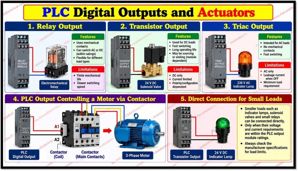
A PLC output normally provides a control signal rather than directly supplying a large motor.
A common arrangement is
PLC output → contactor coil → contactor main contacts → motor.
Smaller loads may be connected directly only when their electrical requirements remain within the output module ratings.
Inductive Loads and Feedback
Contactors, relays and solenoid coils are inductive loads.
When current is interrupted, stored magnetic energy can create a voltage transient.
Suitable suppression reduces stress on switching devices and electronics.
For a suitable DC coil, a flyback diode (or) another appropriate suppression device may be used.
For AC coils, an RC snubber, varistor/MOV (or) another approved suppressor may be appropriate.
Selection should match the coil, switching device, voltage and required operating characteristics.
Feedback can verify a commanded action.
For Example:
After energizing a solenoid to extend a cylinder, the PLC can wait for an extend-position switch.
If the signal does not arrive within the expected time, the PLC can generate a timeout (or) fault.
Reliable I/O Practices
Reliable PLC control needs correctly selected and maintained I/O.
Key practices include:
- Verify sensor voltage, polarity, signal type and sourcing/sinking compatibility.
- Separate power and sensitive signal wiring where appropriate and apply suitable EMC practices.
- Size the 24 V DC supply for the PLC, I/O, sensors, relays and other loads.
- Never exceed PLC output voltage (or) current ratings.
- Apply suitable suppression to inductive loads.
- Use available diagnostics, I/O LEDs, wire-break (or) short-circuit detection, alarms and timeouts.
- Label I/O points & maintain accurate wiring documentation.
- Inspect terminals & field devices according to the maintenance plan.
Simple PLC Control Sequence
The complete process can therefore be summarized as:
PHYSICAL CONDITION
↓
SENSOR
↓
DIGITAL INPUT MODULE
↓
PLC INPUT DATA
↓
PLC PROGRAM
↓
CONTROL DECISION
↓
DIGITAL OUTPUT MODULE
↓
CONTACTOR / RELAY / VALVE
↓
ACTUATOR
↓
PHYSICAL ACTION
↓
FEEDBACK SENSOR (IF USED)
↓
DIGITAL INPUT
↓
PLC
For a motor application:
Start Push Button
↓
PLC DI
↓
PLC Logic
↓
PLC DO
↓
Contactor Coil
↓
Motor Starts
↓
Auxiliary Contact / Running Feedback
↓
PLC DI
Conclusion
A simple PLC control loop follows
Sense → Process → Decide → Act
with Feedback added when confirmation is required.
The fundamental PLC control path can be expressed as:
Sensor → Digital Input → PLC Logic → Digital Output → Actuator → Feedback
The sensor provides field information and the digital input makes it available to the PLC that the program evaluates it and the digital output commands an appropriate device and the actuator generates the physical result.
Reliable operation depends on I/O compatibility, timing, output technology, load ratings, suppression, power-supply design, diagnostics, wiring and safety architecture.

