
1). What is PLC?
PLC – Programmable Logic ControlLER
PLCs are computerized industrial controllers or solid-state control devices used in the automation sector to carry out sequential or discrete logic.
PLCs are a combination of software & hardware. It serves as the brain of the machine (or) system in automation control systems.
The digital electronic device known as a PLC carries out the following fundamental functions.
- Implements particular functions, such as programming logic, sequence, timing, counting, and arithmetic operations, using programmable memory to store instructions.
- Manage technical procedures and electrical devices.
2). What is the function of PLCs in automation?
PLC is used extensively in automation to control and monitor industrial applications.
It contains both hardware & software.
This controller device is able to be executed and operated both automatically and manually. It requires more effort, time, utility, & accurate system operation to function properly.
- It improves the system’s reliability and stability.
- It conducts exact operations in very little time. This can be the reasons that PLC is now widely utilized in industry.
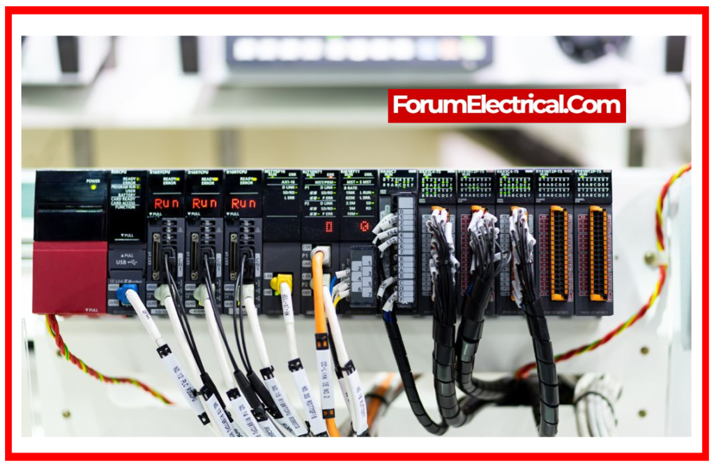
3). What are the different components of a PLC?
PLC has various components. Each component is related to various PLC operations & functions.
Basic components of PLC
- Input & Output Modules: These modules offer input to the PLC & generate output. Input and output might be digital or analog.
- Power Supply: This component is accountable for supplying AC (or) DC power to the PLC.
- Central Processing Unit (CPU): The Central Processing Unit (CPU) stores and executes PLC software applications.
- Memory System: The memory system stores and retrieves information needed for PLC operations.
- Communication Protocol: Multiple devices can be linked to the PLC. Communication protocols are used to transfer information from one component to another.
- PLC Programming (Software Skills): PLC logic must be implemented using a programming language.
These are the 6 fundamental components of a PLC.
4). What are the different types of PLC?
PLCs are classified into 3 types based on how they are construction structure and working:
- Compact PLC
- Modular PLC
- Distributed PLC
5). What are the different PLC automation implementations?
The primary implementations of PLC are in industries; however, other applications of PLC include
- Driving Motors
- Light Lamps
- Button Switches
- Traffic signals
- Water Draining Pumps
- Photo sensors.
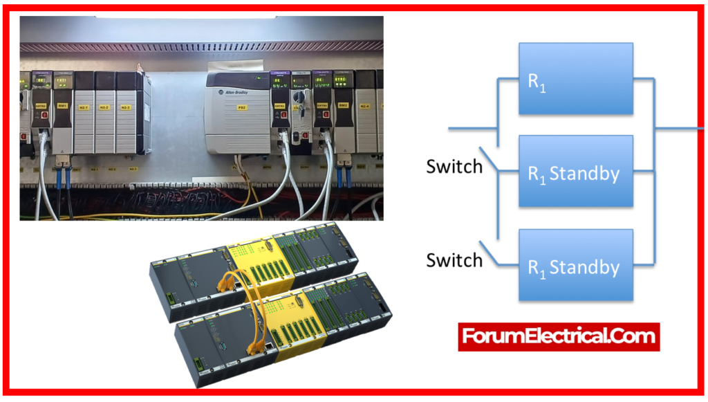
6). What is Redundancy in PLC?
Redundancy is defined as a state of non-usefulness. When PLCs go out of service or have defects, they cannot be utilized.
They become useless & are referred to as redundant. It’s called PLC redundancy.
7). Which are the different brands of PLC?
The different companies have created their own PLC brands. These are a few well-known PLC brands.
- ABB PLC
- AB (Rockwell) PLC
- Siemens PLC
- Delta PLC
- Mitsubishi PLC
- Honeywell PLC
- Omron PLC
- Schneider PLC
- Hitachi PLC
- Fatek PLC
- Bosch PLC
- GE (General Electric) PLC
PLCs made by Siemens and Allen-Bradley (AB) are primarily utilized for projects and educational resources purposes.
8). What is HMI in PLC?
HMI – Human Machine Interface
HMI essentially allows operators to connect (or) communicate with the system they are monitoring.
The HMI displays a graphical representation of the mechanical system’s status and allows direct control over its operation.
Graphical HMI screens are able to be programmed to show the operator all relevant status & control information.
9). What are the different programming languages utilized in PLCs?
The programming language is utilized to write the software that controls the PLC or automation system.
According to the IEC standard, 5 different programming languages are utilized in PLC.
The list of several PLC languages utilized in the industry is as follows.
- Structured Text (ST)
- Ladder Diagram (LD)
- Function Block Diagram (FBD
- Instruction List (IL)
- Sequential Function Charts (SFC)
10). What are the general functions of a PLC?
Sequential Control: PLC converts binary signal input into output that is utilized for sequential technical processing; here, PLC retains all steps in sequential process in the correct order.
Plant Monitoring: A PLC continuously monitors the state of a system and performs the appropriate actions in connection with process under control or displays a notification to the operator.
Shutdown System: The working premise of a PLC is to receive a controlled process input signal, process it in accordance with a program stored in memory, and then generate an output signal to operate the actuator or other equipment.
11). Describe the basic elements of Ladder Logic Programming
Ladder logic has 3 fundamental organizing components:
RUNG: A function is used to write ladder logic instructions. The CPU runs the scan program from left to right, ladder by ladder from top to bottom.
INSTRUCTION: Ladder logic Instructions are separated into two parts.
- Input Instructions: Located on the left side of ladder Check, compare, or specify conditions.
- Output Instructions: Located on the right side. Perform some activity.
BRANCHES: Branches are used in ladder logic to build several paths that directly read the state of inputs & outputs.
12). What is LD in the PLC?
LD – Ladder Diagram
It is the most popular and widely acknowledged programming language for PLCs.
It is simple to develop PLC logic with LD because it has a graphical user interface.
LD is also known as “Ladder Diagram Language” or “Ladder Logic Language”.
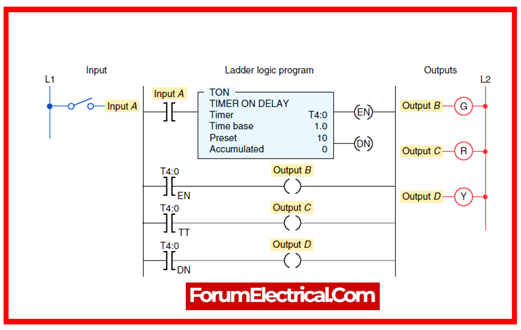
13). What is the Timer?
The timer is the most important PLC command.
The timer is used to activate & control devices for a set period of time. The programmer may set the timer according to the project requirements.
14). What function does a power supply perform in a PLC system?
Within a PLC system, the power supply is in charge of supplying the necessary energy for the processor, input/output (I/O) modules, and communication components.
Its input voltage typically ranges from 120 to 230 volts (V) (or) 24 V DC.
It returns to the plane with an output of around 5 V DC at 2–5 A.
15). What are Reed Relays?
Reed relays are electrical switches which utilize an electromagnet to open and close two contacts.
They have a coil looped around a reed switch with overlapping blades, or ‘reeds’.
When power is provided to the coil, it generates a magnetic field that draws these components together, forming contact and allowing electricity to pass through the relay.
16). What is a rack (or) chassis in a PLC system?
Rack or chassis refers to the hardware assembly of all modules of a modular PLC, such as the power module, communication module, CPU, & input & output modules.
It enables an even distribution of power supply to all modules and serves as a communication link between the CPU & the other modules.
17). What is the difference between active and passive backplanes in PLC?
A backplane is used in PLC racks to provide power & interconnectivity between numerous modules.
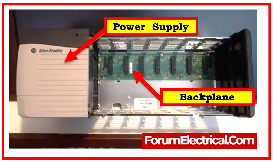
Communication is handled by attaching one (or) more expansion boards to the backplane.
| Active Backplane | Passive Backplane |
| An active backplane is equipped with several slots as well as the electronics required to govern module communications. | The passive backplane consists of merely bus connectors & a minimum of extra electronics. |
18). What are varied types of PLC Timers?
In general, three basic types of timers are utilized:
- On Delay Timer
- Off Delay Timer
- Retentive On Timer (RTO)
19). What is a counter module in PLC?
The counter command is useful for sequentially counting digital numbers. It’s an aspect of the mathematical function.
A PLC counter is a function block that counts up (or) down until it hits a set limit. When the limit is met, the output is set. Counting, however, is commonly employed in PLC programming. You will frequently be required to count several things.
20). What are the various types of counters utilized in PLC?
PLC counters are classified into three types:
- Up Counter
- Down Counter
- Up/Down Counter
Mostly, the up/down counter is utilized in PLC programming.
21). How to test or commission a PLC system?
- Make sure that every cable connecting the PLC to the plant is full, safe, complies with all local regulations, & meets all necessary specifications.
- Verifying that the voltage setting that the PLC is set for is met by the entire incoming power supply.
- Verify that the settings on all safety equipment are appropriate for the trip.
- Make sure the emergency stop button functions.
- Ensure that every input/output device is providing the right signals & is connected to the appropriate input/output locations.
- Loading & testing the software.
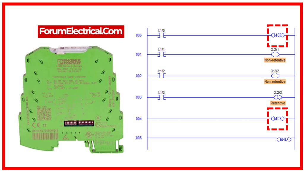
22). What is MCR?
MCR – Master Control Relay
It is a type of instruction found in Siemens’ PLC software. This instruction is utilized to terminate the process.
Some different types of MCR instruction include:
- MCRA (Master Control Relay Active),
- MCRD (Master Control Relay Deactive),
- MCR> (Master Control Relay Greater),
- MCR< (Master Control Relay Less).
23). What are the advantages of a PLC over a hardware relay?
- PLC exists in both software & hardware forms. However, relay occurs only on the hardware basis.
- PLCs are easier to monitor and control than relays.
- The problem with PLC software is simple to identify.
- PLCs provide more operating capabilities and functionality than relays.
- PLCs are more flexible and reliable than relays.
- The PLC programming logic is easier to alter and implement than the relay.
24). What are the disadvantages of PLC?
- With PLC, you can only run one program at a time. You cannot run numerous PLC programs at the same time.
- There are certain restrictions to using PLC in the workplace.
- Performance decreases in some conditions, such as high temperatures and vibrations.
25). What are the applications of PLC?
- PLC is used in industries such as steel, glass, cement, paper mills, coal mines, automobiles, chemical industries, textile industries, robotic systems, and food processing.
- It is utilized in power plants that transmit and distribute electricity.
- It is utilized for household uses in remote sensing devices.
- PLC can also be used in educational settings, such as academic or research initiatives.
- PLC is primarily utilized for commercial & educational (academic) use.