
Controlling the speed of an electric motor is important in a wide range of industrial applications, including
- HVAC systems,
- Conveyors, and
- Pump operations.
Utilizing a Variable Frequency Drive (VFD) is certainly one of the most dependable and accessible methods of application.
VFDs control the speed of motors. The controller’s complexity can range from a simple, manually controlled control panel to a more complicated PLC capable of automating control depending on system variables such as flow, level, or pressure.
Three-phase induction motors powered by line voltage produce generally smooth sine waves with frequencies ranging from 50 to 60 Hz, depending on location.
- Without the use of a variable frequency drive (VFD), the speed of the motor is largely constant and only slightly fluctuates with load owing to motor slip.
- With a variable frequency drive (VFD) controls the voltage and current provided to the motor by turning ON/OFF IGBT transistors.
The voltage amplitude & current values is determined by the frequency of switching and the IGBTs’ on and off times.
This indicates that the voltage & current numbers increase as the switches remain on longer than they are off.
The speed and torque of an alternating current motor can be altered by a Variable Frequency Drive (VFD), which modifies the frequency and voltage that is delivered to the motor.
Working of a Variable Frequency Drive (VFD)
A VFD converts fixed-frequency AC power into variable-frequency AC power, allowing for precise control of the motor speed.
This includes three major steps:
1). Rectification
Incoming alternating current sources, which are commonly three-phase 415V or 230V, are converted into direct current by a diode bridge rectifier during this step.
The frequency component is removed in this step, and the alternating current is transformed into a DC voltage that is constant.
2). DC Link (Filtering)
The rectifier’s DC output is routed via a filter, typically composed of capacitors & inductors, to smooth out ripples & stabilize the voltage.
3). Inversion
The filtered DC is then sent into an inverter circuit, which is commonly constructed with IGBTs (Insulated Gate Bipolar Transistor).
The inverter switches at a high frequency (PWM – Pulse Width Modulation) to generate AC power with a changeable frequency & voltage, which controls the motor speed.
Motor Speed ∝ Supply Frequency
Ex: if a motor runs at 1500 RPM at 50 Hz, lowering the frequency to 25 Hz reduces the speed to around 750 RPM.
Motor Speed Control Flow Diagram using VFD
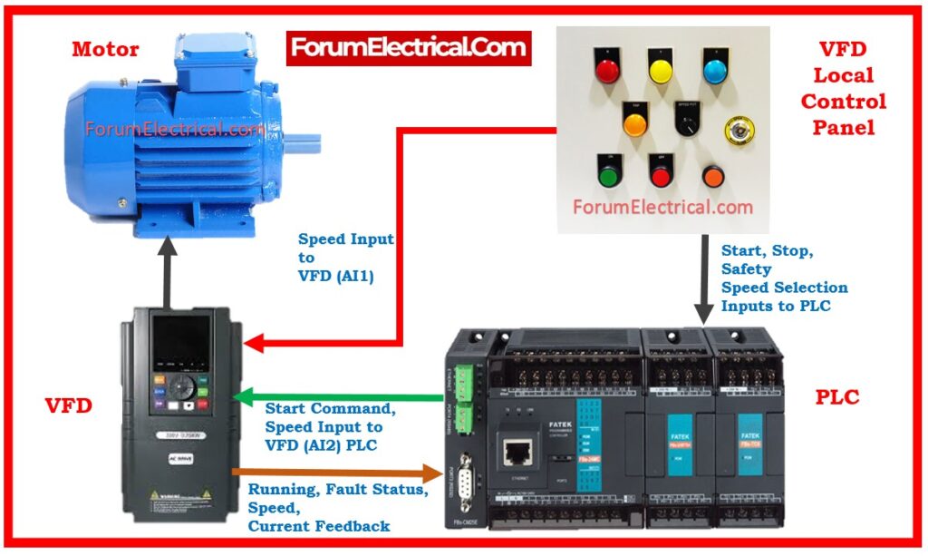
Key Components:
- AC Motor
- PLC
- Local Control Panel
1). Component Function
AC Motor
AC Motor receives power from the VFD and operates at the specified speed.
VFDs regulate voltage & frequency output according to control signals.
PLC
PLC (Programmable Logic Controller) sends operational commands, including speed setpoints and start/stop signals.
Local Control Panel
The Local Control Panel features
- Manual controls,
- Status indicators, &
- Safety switches.
2). Signal Flow
PLC to VFD: Sends analog (0-10V or 4-20mA) or digital control signals (Modbus/Profibus).
VFD to Motor: Provides AC power with controlled frequency & voltage.
Motor to VFD: Sends feedback on current, temperature, and fault status.
VFD to PLC: Sends status, faults, and running speed via I/O (or) communication protocols.
Speed Control of Motor by VFD
There are various types of motor speed control systems accessible in the electrical field. Increased use of VFD systems to control motor speed.
To calculate variable frequency drive (VFD) speed (RPM), utilize this formula:
N = 120 x Frequency/Number of Poles
N = 120 x f/P
Where
N – Motor speed in rpm
f – Supply frequency
P – Number of poles in motor.
Since P and 120 are constant.
As a result, adjusting the supply frequency allows us to change the motor speed.
Advantages of VFD-Based Motor Control
- Reduces energy usage by adjusting motor speed based on process demand. Suitable for centrifugal pumps & fans.
- VFDs allow gentle start and stop functions, which reduce mechanical stress on equipment and eliminate the need for star-delta (or) auto-transformer starters.
- Provides exact control over motor speed, even under variable load circumstances. Useful for conveyors, textile machines, & elevators.
- Integration with PLC or SCADA systems enables real-time automation & remote monitoring.
- By regulating the speed and ensuring a smooth start, motor bearings, belts, and gears are subjected to less wear and tear.
Disadvantages of VFD-Based Motor Control
- VFDs are more expensive than conventional starters and may necessitate additional components like as filters, reactors, & enclosures.
- VFDs may introduce electrical harmonics into the power system, that can destroy surrounding sensitive equipment if not adequately filtered.
- High switching frequencies cause electromagnetic interference. Shielded cables and correct grounding are essential to mitigate this issue.
- Proper parameter configuration (e.g., acceleration time, maximum/minimum frequency, torque restrictions) necessitates skilled staff.
Applications of VFD-Based Motor Control
- Industrial Automation: Conveyor systems, mixers, and dosing pumps
- HVAC Systems: Fan & pump control for the energy-efficient building management
- Water Treatment Plants: Pump control based on level, pressure, or flow feedback
- Textile Industry: Speed variation in looms and winders
- Elevators & Cranes: Smooth motion & accurate speed control
- Compressors & Blowers: Load-dependent motor speed regulation
Related Standards
- IEC 61800-3: EMC requirements for the electrical drive systems with the adjustable speeds,
- UL 508C: US-safety standard for the power conversion equipment,
- IEC 60034-25: International standard – Motor specifications when used with VFDs.
What is the Formula for VFD speed control?
Use this formula to determine the revolutions per minute (RPM) of a variable frequency drive (VFD):
Formula
RPM = 120 x Frequency/Number of Poles
For Slip calculation, utilize this formula:
Formula
Slip (%) = ((Synchronous Speed – Rated Full Load Speed) / Synchronous Speed) x 100%.


. Learn about VFD working principles, control flow, advantages, disadvantages, applications, & industry standards for energy-efficient and precise motor speed regulation.)