
- What is the function of a Capacitor?
- Why it is necessary to test a capacitor?
- Safety Precautions before Test a Capacitor
- How to Discharge the Capacitor?
- 6 Ways to Test a Capacitor
- TEST 1: Testing a Capacitor with a Multimeter and a Capacitance Setting
- Test 2: Using a Multimeter to Test a Capacitor Without a Capacitance Setting
- Test 3: Capacitor Testing by Measuring the Time Constant
- Test 4: Using Voltmeter to Test a Capacitor
- Test 5: Analog Multimeter Capacitor Testing (AVO Meter)
- Test 6: Capacitor Lead Shorting (Traditional Method)
What is the function of a Capacitor?
A capacitor is an electrical energy storage device.A capacitor in an electrical field stores electrical energy.
It is a docile electronic component with two terminals. Capacitance is referred to as the capacitor effect.
Capacitors are often constructed differently depending on their application. Capacitors are in different type of shapes and sizes.
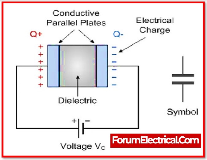
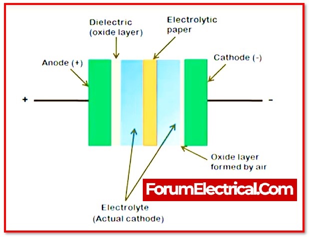
Capacitors are typically made up of metallic plates on both ends with a dielectric medium in between them.
Metallic plates serve as electric conductors and can range from foil to electrolyte to thin-film to metallic plates.
The dielectric medium in between helps to increase the capacitor’s charge capacity. Dielectrics include ceramic, mica, glass, and air.
Capacitors are frequently used in electrical circuits, while resistor is known to dissipate energy, capacitors frequently do not dissipate energy.
Capacitors dissipate a small (minimum) amount of energy in practical applications.
Why it is necessary to test a capacitor?
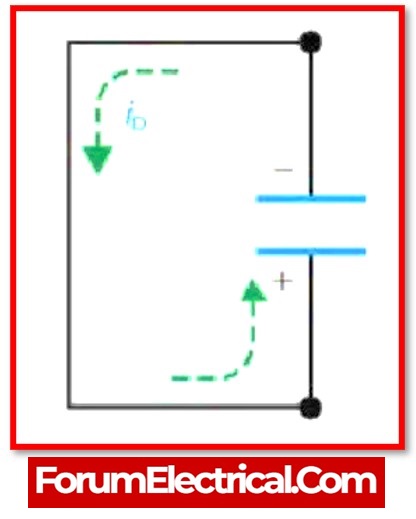
When a capacitor is connected to an active circuit – a circuit with active current flowing through it, charge starts to accumulate in the capacitor (one of its plates), and when the plate of the capacitor can no longer take on any additional charge, the capacitor has reached its full charge capacity and is available to be used.
If the circuit demands this charge (for example, a bypass capacitor), the capacitor returns the charge to the circuit and this process continues till the charge is completely released (or) the circuit stops demanding.
These functions are known as capacitor charging and discharge.
- Electrolytic and
- Non-electrolytic capacitors
are the two types of capacitors.
A capacitor, like every electrical and electronic component, is highly susceptible to voltage spikes, which can permanently damage the capacitors.
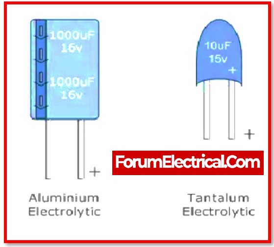
Failure of electrolytic capacitors typically occurs when the capacitor discharges too much current too quickly or when the capacitor becomes too dry to hold a charge.
On the other side, non-electrolytic capacitors are susceptible to failure as a result of leakages.
There are several methods for determining whether or not a capacitor is working properly.
Let’s look at some methods for testing a capacitor.
Safety Precautions before Test a Capacitor
When testing capacitors, especially those with high voltages, safety comes first.
Taking these procedures is vital to protect yourself & ensure reliable testing results.
- Circuit – Power Off: Before starting any testing, check sure the circuit is turned off and unplugged. This phase avoids the possibility of electric shock & protects the equipment from harm throughout the testing procedure.
- Discharge the Capacitor: Capacitors can hold a charge even when the power is switched off, offering a major risk of electric shock. To safely discharge the capacitor, use a discharge tool (such as a resistor). Connect the resistor to the capacitor terminals & hold it in place for a few seconds to ensure that the stored charge is gradually and securely released.
- Wear Insulated Gloves: Insulated gloves are essential for protecting oneself against electric shocks. High-voltage capacitors can be unsafe, therefore use suitable safety gear when handling and testing them.
- Check for Residual Voltage: Although after discharging the capacitor, ensure that no residual voltage remains. Before handling the capacitor, check it for any remaining voltage with a multimeter. This procedure provides an additional degree of protection by ensuring that the capacitor is fully discharged and safe to touch.
By following these safety procedures, you can reduce the dangers connected with capacitor testing, resulting in a safe and efficient process. These practices are critical for ensuring a safe working environment & preventing accidents, making them an essential component of every engineer’s skill set.
How to Discharge the Capacitor?
Before examining various methods for testing capacitors, it is necessary to analyse how to discharge a capacitor properly.
This is crucial because capacitors can retain their charge even if the power supply is cut.
If the capacitor is not properly discharged and users accidentally touch its leads, it will discharge through the body, causing an electric shock.
Using the Screwdriver
This method is not recommended because sparks will be produced during discharge, which could cause burns or other damage.
If the capacitor is in the circuit (on the PCB), de-solder it properly and avoid touching the capacitor’s terminals. Hold in one side an insulated screwdriver (with a longer handle).
With the other side, grasp the capacitor and touch the metal portion of the screwdriver to the capacitor’s terminals.
As justification of an electric discharge, users will observe sparks and hear a crackling sound. Repeat a few times to ensure the capacitor has been completely discharged.
Using the Discharge Resistor (Bleeder Resistor)
When a Resistor (Bleeder Resistor) is placed in parallel with the output capacitor, the remaining charge in the capacitor is discharged through the resistor when the power is turned off.
Connect a resistor with a large value (kilo Ohms) and a high-power rating (such as 5W) across the capacitor’s terminals.
Rather than connecting directly, can use wires with crocodile clips on the both ends.
Use a multimeter to monitor the voltage across the capacitor’s terminals as the capacitor slowly discharges.
Use Capacitor Safety Discharge Calculator at the starting point.
6 Ways to Test a Capacitor
TEST 1: Testing a Capacitor with a Multimeter and a Capacitance Setting
This is one of the simplest, quickest, and most accurate methods of testing a capacitor. Digital Multimeter with a Capacitance Meter used for testing.
This feature is available on the majority of mid- and high-end digital multimeters.
The capacitance meter on digital multimeters frequently displays the capacitance of the capacitor, but only a few metres display other parameters such as ESR, leakage, and so on.
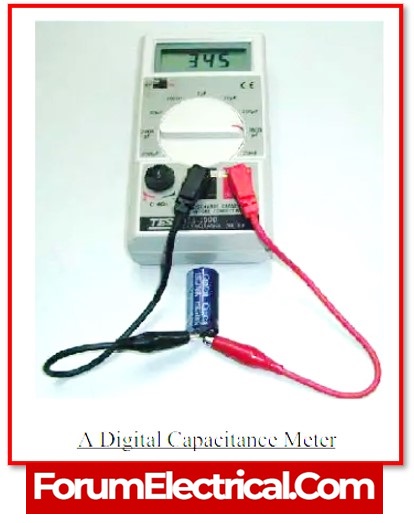
The steps below can be used to test a capacitor using a Digital Multimeter with Capacitance Meter.
- Disconnect capacitor from the circuit board and completely discharge it.
- Make a note of the capacitor ratings if they are visible on the body. The capacitance in Farads (micro-Farads) is typically printed on the body alongside the voltage ratings.
- Set the knob on the Digital Multimeter for capacitance measurement.
- Connect the multimeter probes to the capacitor’s terminals. If the capacitor is polarised, connect the red probe to the positive terminal and the black probe to the negative terminal . Non-polarized capacitors can be connected either way because they lack polarity.
- Check the Digital Multimeter readings now. If the multimeter readings are close to the actual values (as stated on the capacitor), the capacitor is considered good.
- If the difference between the actual value and the measured reading is significant, the capacitor is dead and should be replaced.
- Capacitors with capacitances ranging from a few nano-farads to hundreds of microfarads can be measured using this method.
Test 2: Using a Multimeter to Test a Capacitor Without a Capacitance Setting
Most low-cost digital multimeters do not include a capacitance meter or capacitance settings.
- Disconnect capacitor from the circuit (or) board and ensure that it is fully discharged.
- Set the Multimeter to measure resistance, for example, by turning the knob to Ohm or Resistance Settings. If ananalogmultimeter has multiple resistance measurement ranges, choose the highest range (usually 20 K to 200 K).
- Connect the multimeter probes to the capacitor’s leads (red to ‘+’ and black to ‘-’ in case of polarised capacitors).
- The Digital Multimeter will display a resistance reading, and it will soon display the resistance of an open circuit i.e., infinity.
- Take note of the reading that was displayed for that brief period of time.
- Repeat the test several times after disconnecting the capacitor from the multimeter.
- For a good capacitor, each test attempt should yield a similar result on the display.
- If the resistance does not change in the subsequent tests, the capacitor is dead.
This method of testing the capacitor may not be precise, but it can distinguish between good and bad capacitors. This method also does not provide the capacitor’s capacitance.
Test 3: Capacitor Testing by Measuring the Time Constant
This method is only useful if we know the capacitance value and want to determine whether a capacitor is good or bad.
In this method, can measure the capacitor’s Time Constant and derive the capacitance from the measured time.
If the measured and actual capacitances are similar, the capacitor is in good condition.
TIME CONSTANT: A capacitor’s time constant is the time it takes to charge to 63.2% of the applied voltage when charged through the known resistor. If C is Capacitance and R is a known Resistor, then τ = RC provides the Time Constant TC (Greek Alphabet Tau – τ ).
- Ensure that the capacitor is properly discharged and disconnected from the board.
- Connect a known resistor in series with the capacitor (typically a 10 K resistor).
- Connect a known voltage power supply to complete the circuit.
- Switch on the power supply and time how long it takes the capacitor to charge to 63.2% of the supply voltage.
- For example, if the supply voltage is 12V, 63.2% of that is approximately 7.6V.
- Measure the capacitance based on the time and resistance and compare it to the value printed on the capacitor.
- If they are similar or nearly equal, the capacitor is in good working order. If the difference is significant, must replace the capacitor.
- It is also possible to calculate the discharge time. In this case, the capacitor’s time to discharge to 36.8% of its peak voltage can be measured.
Test 4: Using Voltmeter to Test a Capacitor
All capacitors have a maximum voltage rating that can be applied to them. Use the voltage rating of a capacitor for this method of testing a capacitor.
- Disconnect capacitor from the circuit or board and discharge it properly.
- On the capacitor, look for the voltage rating. It will usually be stated as 16V, 25V, 50V, and so on. This is the highest voltage the capacitor can withstand.
- Connect the capacitor’s leads to a power supply or a battery, but make sure the voltage is less than the maximum rating.
- A 9V battery, for example, can be used on a capacitor with a maximum voltage rating of 16V.
- If have a bench power supply, can set a voltage lower than the capacitor’s rated voltage.
- Charge the capacitor for 4 to 5 seconds and then turn off the power.
- Measure the voltage across the capacitor with the digital multimeter set to DC Voltmeter settings. Connect the voltmeter and capacitor’s appropriate terminals.
- A good capacitor’s initial voltage reading on the multimeter should be near to the supplied voltage. If the difference is significant, the capacitor is bad.
Only initial reading on the multimeter must be considered, as the value will gradually decrease. This is completely normal.
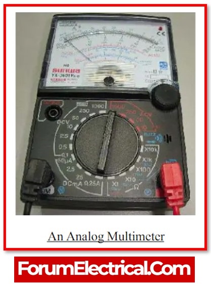
Test 5: Analog Multimeter Capacitor Testing (AVO Meter)
Analog Multimeters, like Digital Multimeters, can measure a variety of quantities such as current (A), voltage (V), and resistance (O). Users use the Ohmmeter functionality of an analogue multimeter to test a capacitor.
- Disconnect and discharge the capacitor as usual. Users can discharge a capacitor by simply shorting the leads, but a load such as a high wattage resistor or an LED is an effective method.
- Set the Analog Multimeter to Ohmmeter and, if there are multiple ranges, select the highest range.
- Connect the capacitor leads to the multimeter probes and read the results on the multimeter.
- The resistance of a good capacitor will be low at first and gradually increase.
- If the resistance is always low, the capacitor is a Shorted Capacitor, and it must be replaced.
- The capacitor is an Open Capacitor if there is no movement of the needle or if the resistance always shows a higher value.
- This test is applicable to both through-hole and surface-mount capacitors.
Test 6: Capacitor Lead Shorting (Traditional Method)
This method is one of the oldest methods for testing a capacitor to determine whether it is good or undesirable.
Precaution: This method is extremely dangerous and should only be used by professionals. It should only be used as a last method to test the capacitor.
Safety: The method is described in terms of a 230V AC supply. However, for safety reasons, a 24V DC power supply can be used. Even with 230V AC, limit the current with a series resistor (high watts rated).
- The capacitor being tested must be disconnected from the circuit and discharged properly.
- Connect the capacitor’s leads to the supply terminal. Only non-polarized capacitors can be used with 230V AC.
- Both polarised and non-polarized capacitors can be used for 24V DC, but polarised capacitors must be properly connected.
- Turn on the power supply for a brief period of time (typically 1 to 5 seconds) and then turn it off. Disconnect the power supply’s capacitor leads.
- Using a metal contact, connect the capacitor’s terminals. Make sure that are properly insulated.
- The capacitor’s spark can be used to determine the capacitor’s condition. If the spark is large and strong, the capacitor is in good working order.
- If the spark is small and weak, the capacitor must be replaced.
- This method is appropriate for capacitors with lower capacitances. This method can only show the capacitor can hold a charge.