Selection of VFD
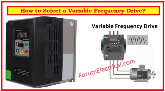
Selecting the ideal VFD (or) motor controller can be slightly difficult due to the numerous factors involved in each application and system.
Here are some useful recommendations and suggestions to assist you in choosing the appropriate drive.
With a deeper understanding of your application’s requirements, the complexity of the unclear should hopefully reduce.
The information will be personalized to the requirements of your system & application, such as:
- Load Type for VFD
- Motor Details
- Power Supply
- Methods for Controlling VFD
- Speed Reference Alternatives
- Efficiency and Power Factor
- Protection & Electrical Stability (Power Quality)
- Harmonics
- Horsepower (HP)
- Full-Load Amps (FLA)
Load Type for VFD
If the equipment being operated is centrifugal in nature, such as a fan (or) pump, then a variable-torque drive would be a more appropriate selection.
The main advantage of Variable Frequency Drives (VFDs) for centrifugal applications is energy efficiency, with variable torque drives providing the highest level of energy savings.
Ex: A fan requires a lower amount of torque when operating at 50% speed compared to when it is running at its maximum speed. Variable torque operation enables the motor to exert torque in accordance with the required amount, leading to decreased energy consumption.
- Conveyors,
- Positive displacement pumps,
- Punch presses,
- Extruders, & other related applications
necessitate a consistent level of torque regardless of speed.
If there is a situation where constant torque variable frequency drives might be more suitable for the task.
A continuous torque drive should possess an overload current capability of at least 150% for a duration of one minute or longer. Variable torque variable frequency drives require an overload current capability of only 120% for one minute, as centrifugal applications often do not above the rated current.
If you are purchasing a Variable Frequency Drive (VFD) for a system that requires precise process control, it is advisable to consider buying a sensor less vector or flux vector VFD. These types of VFDs offer a high level of accuracy in
- Controlling speed,
- Torque, &
- Positioning.
Motor Details
To pick the appropriate variable frequency drive, the following motor information is required:
Maximum current rating under full load conditions. Utilizing a motor’s horsepower as a basis for sizing variable frequency drives is inaccurate.
In general, it is not recommended to operate a motor at a speed lower than 20% of its maximum allowable speed.

If the motor is operated at a speed lower than this, without auxiliary motor cooling, it will experience overheating. If the motor needs to be used at lower rates, it is advisable to utilize auxiliary motor cooling.
In order to get the appropriate capacity for a variable frequency drive that can regulate multiple motors, simply sum up the full-load amp ratings of each individual motor. All motors operated by a single drive must possess an identical voltage rating.
Power Supply
If uninterrupted operation is essential, then the following details should be specified:
- Voltage fluctuation within a range of +/- 10%.
- Frequency variation within a range of +/- 3%.
Voltage sag ride-through is required for the following:
- Zero voltage for one cycle.
- Apply a voltage of 60% for a duration of 10 cycles. The voltage remains at a steady level of 87%.
- If you need to provide a 3-phase drive with single-phase power, it is necessary to reduce the drive’s capacity by 25% to 50% of its current-handling capability.
This may result in the requirement to select a larger-sized drive.
Methods for Controlling VFD
Using 2-wire control, the variable frequency drive may be operated with a single switch. An open switch halts the operation, while a closed switch initiates the operation.
2-wire control is mostly utilized in HVAC applications due to its ability to sustain the RUN command to the drive even in the event of a power outage, allowing VFD to immediately resume operation once power is restored.
In addition, the use of 2-wire control enables drives equipped with “power loss ride-through” capability to continue operating for a duration of 2 seconds or less in the event of a power drop.
The 3-wire control system utilizes a pair of switches to operate the drive. A single switch is required to halt the operation, while another switch is necessary to initiate the variable frequency drive. An auxiliary contact is able to “seal in” the RUN command right from the beginning, similar to traditional motor starters.
Speed Reference Alternatives
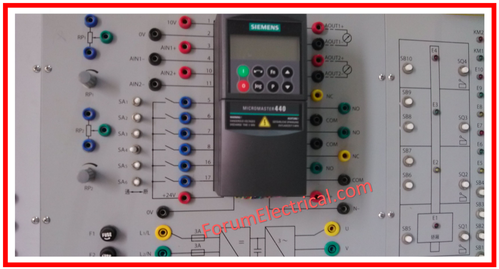
Speed Potentiometers: Variable resistor used to control the speed of a device. It enables the operator to adjust the motor speed using a potentiometer.

Digital Programming / Display Unit: It enables the operator to program & resolve issues with the drive by entering values through a keypad equipped with either an LED or LCD display unit. The display also allows for monitoring of the drive operation.
An analog signal follower is a device that tracks and replicates an analog signal.
The variable frequency drives require an isolated input and can be powered by either a 4-20mA or 0-10VDC signal.
To ensure proper functioning, it is necessary to utilize a twisted/shielded pair of wires and keep them away from any 3-phase AC power sources. Speed selection with a selector switch.
It enables the operator to choose from multiple preconfigured speeds. It can also be utilized in cases when the speed is being adjusted through a Programmable Logic Controller (PLC) and there is no analog output option.
Serial communications: It enable variable frequency drives to establish communication on a network, including PROFIBUS, MODBUS, DEVICENET, or METASYS. This allows for the coordination and monitoring of drive operation from a PC.
Efficiency and Power Factor
Efficiency & power factor are two important factors to consider in electrical systems.
An optimal drive should possess an efficiency rating of 95% or higher when operating at maximum capacity. Variable frequency drives should provide a system power factor of at least 95% over the whole operational speed range. This is important to prevent penalties from the power provider, reduce energy costs, and protect equipment, particularly motors.
Protection & Electrical Stability (Power Quality)
The motor is experiencing an overload that will cause it to trip instantaneously. This is due to an excessive current flowing through the motor.
The potential issues that can occur are
- Over voltage,
- Under voltage,
- Over temperature,
- Ground fault, and
- Control or microprocessor error.
The protective circuits are designed to ensure a systematic shutdown of the VFD, indicate any failure situation, and necessitate a human reset (except for under voltage) before restarting.
The system will automatically restart if power is restored to normal levels following an under voltage caused by a power loss. The historical record of the preceding three mistakes will be retained in memory for future testing.
If a system that has been constructed is necessary.
Additionally, it is necessary to have externally-operated short circuit protection, a door-interlocked fused disconnect, a circuit breaker or motor circuit protector (MCP) with a minimum rating of 65,000 AIC, & a door-interlocked handle that can be locked.
Harmonics
Harmonics refer to the mathematical concept of the relationship between the frequencies of different waves or vibrations.
The drive/system must adhere to the specifications given in IEEE 519-1992.
Harmonics are important considerations when selecting Variable Frequency Drives (VFDs) since they can have a major impact on the performance and dependability of both the drive and the electrical system it is connected with. Because of their nonlinear power conversion process, VFDs generate harmonics by definition, which can result in
- Distorted waveforms &
- Increased total harmonic distortion (THD) in the system.
When choosing a VFD, it is critical to consider the harmonic content it generates and ensure compliance with applicable standards and regulations defining allowable harmonic levels in power systems.
Harmonics can have an impact on system components including
- Motors,
- Cables, and
- Control equipment,
Therefore, compatibility and resilience must be carefully considered.
Furthermore, treating harmonics by filtering (or) mitigation measures may entail additional expenses, emphasizing the significance of combining performance requirements with limited financial resources.
Overall, understanding the consequences of harmonics and their management is essential for selecting the best VFD for a certain application, providing optimal performance & reliability with respect to power quality.
Horsepower (HP)
Although it is essential to design the VFD based on the FLA of the motor(s) under control, understanding the horsepower of the load is an ideal way of looking for drives that may meet your application, which can then be narrowed down by other criteria.
Full-Load Amps (FLA)
This is probably one of the most significant components of information to acquire. To properly size a VFD, use the FLA instead of horsepower ratings. You should compare FLA of the motor with amp ratings of each VFD that you’re considering. This is particularly essential if you have a load that requires steady torque or is difficult to start.
What is the benefit of using a Variable Frequency Drive?
Reduce Energy Consumption & Costs
If your application does not require full speed operation, you can save energy by controlling the motor using a variable frequency drive, which is one of Variable Frequency Drives’ advantages. VFDs allow you to adjust the speed of motor-driven equipment to meet the load. This cannot be accomplished using any other means of controlling an AC electric motor.
Electric motor systems consider more than 65% of total industrial power usage today. Enhancing motor control systems by installing (or) upgrading to VFDs can cut your facility’s energy consumption by up to 70%. Additionally, the use of VFDs increases product quality while lowering production costs. When energy saving tax incentives and utility rebates are combined, returns upon investment for VFD installations can be as low as 6 months.
Increase Productivity by tightening Process Control
By operating the motors at the most effective speed for your application, you will make fewer mistakes and boost production levels, resulting in more income for your organization. On conveyors and belts, you avoid jerks during startup, allowing for high throughput.
Increase Equipment Life & reduce Maintenance
When your equipment is controlled by VFDs, which provide appropriate motor application speed, it lasts longer and requires fewer maintenance. Because of the VFD’s optimal regulation of the motor’s frequency and voltage, it provides superior protection for your motor against electro thermal overloads, phase protection, undervoltage, overvoltage, and so on. If you start a load with a VFD, you avoid the “instant shock” of across-the-line starting and instead start slowly, reducing belt, gear, and bearing wear. It also works well to lessen and eliminate water hammer since it allows for smooth accelerating and deceleration cycles.


