
- What is Fluxing in Transformers?
- What is Over-Fluxing?
- Causes of Over-fluxing in Transformers
- Effects of Over Fluxing in Transformers
- Tabulation
- Stipulated Withstand-Duration of Over Fluxing in Transformers
- Protection against Over fluxing (v/f – Protection) in Transformer
- Why is Over Fluxing harmful for the Transformer?
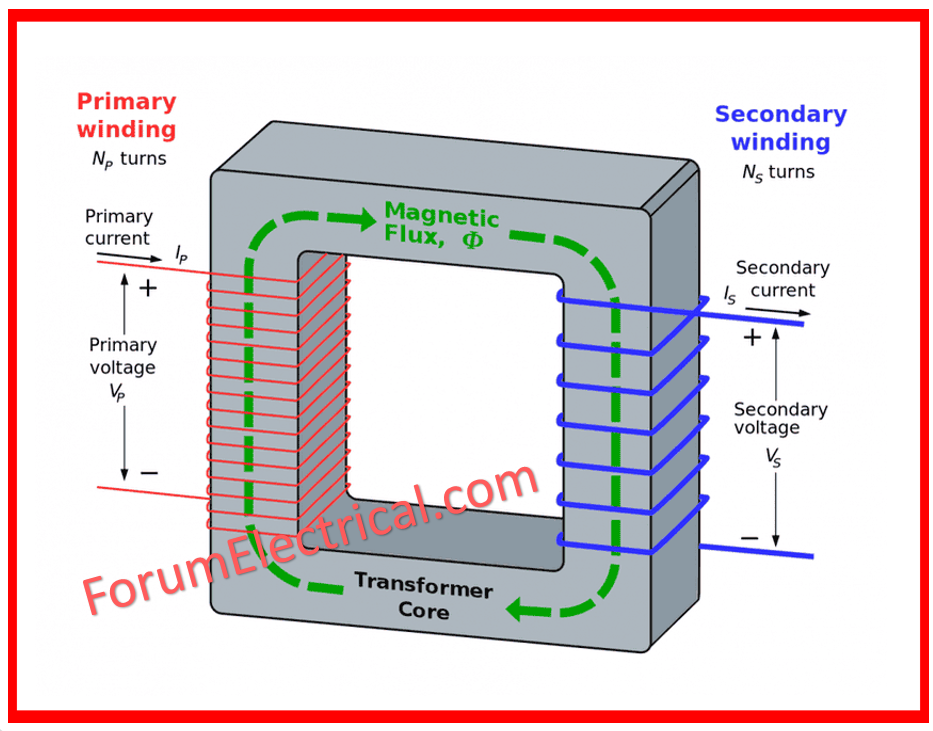
What is Fluxing in Transformers?
Flux is the magnetic flux or magnetic field generated in the iron core of a transformer by the alternating current (AC) current flowing through the primary winding.
AC delivered to the primary creates a continually changing magnetic field, which induces an AC voltage & current in the transformer’s secondary winding.
What is Over-Fluxing?
Over-fluxing is a condition in electrical systems, specifically transformers, in which the magnetic flux exceeds its scheduled or intended level. Magnetic flux is a measurement of the number of magnetic field lines that travel through a surface and is an important metric in transformer functioning.
Magnetic Flux α Voltage/Frequency
Causes of Over-fluxing in Transformers
According to current transformer design procedure, the peak rated value of flux density is maintained between 1.7 and 1.8 Tesla, whereas the saturation flux density of the CRGD steel sheet of the core of the transformer is between 1.9 and 2 Tesla, which corresponds to around 1.1 times the rating.
If a power transformer is required to carry rather than swallow more than the above-mentioned flux density due to its design restrictions, the transformer is considered to have undergone over fluxing, which has a negative impact on its functioning and lifespan.
A transformer has certain over-excitation capacity, which is determined by the design and saturation flux densities, as well as the thermal time constants of heated component parts.
The I.S. (Indian Standard) specification for electrical power transformers does not specify the short time permitted over excitation, but it does state, in an indirect manner, as the maximum over fluxing in the transformer must not exceed 110%.
A transformer’s flux density can be expressed as:
B = C (V/f)
Where,
f- Frequency and
C -Constant
The magnetic flux density is thus proportional to the ratio of voltage & frequency (V/f). Over fluxing can thus occur as a result of an increase in voltage (or) a drop in frequency, or both.
Over fluxing is more likely in step-up transformers in power plants than in step down transformers at substations, where voltage & frequency are often constant.
Over-fluxing also happens in step-down transformers (substation transformers) under extreme system circumstances.
The over fluxing relays are set up so that the transformer fails to trip for any transient over flux condition, ensuring power system stability.
However, it should trip immediately as the length & severity of the problem exceeds the set safe threshold.
There are various causes of transformer overfluxing, but some frequent causes are listed below for reference.
- Overvoltage is caused by sudden load rejection.
- Low frequency power generation
- Transmission lines are lightly loaded.
- The transmission mechanism lacks proper shunt correction. etc.
Effects of Over Fluxing in Transformers
Under normal conditions, the flux in a transformer is contained to its core due to its high permeability in comparison to the adjacent volume. When the flux density exceeds the saturation point, a significant quantity of flux is diverted to steel structural elements and released into the atmosphere. At saturation flux density, the core steel will overheat.
Structural steel parts that are nu-laminated and not intended to carry magnetic flux will heat quickly.
Flux flowing in unplanned air pathways can connect conducting loops in the
- Windings,
- Loads,
- Tank foundation at the bottom of the core, and
- Structural sections,
resulting in dangerous temperature increases.
Due to the extensive harmonics of the exciting current, excessive fluxing can heat the inner windings adequately.
It is evident that the amounts of loss that occur in the winding under high excitation cannot be allowed indefinitely if the damage is to be repaired.
Physical evidence of damage caused by excess fluxing varies depending on the degree of over-excitation, the time applied, and the transformer’s specific design.
Tabulation
The table below describes such physical injury and its expected implications.
| S.No | Components | Occurrence | Effect |
| 1 | Lead conductors | The conductor insulation discoloration (or) support, as well as gas evolution. | Insulation is electrically and mechanically weakened, as is the support. |
| 2 | Metallic support & surface structure for the core and coils | Discoloration of metallic components and surrounding insulation. Possible carbonized substance in oil. The evolution of the combustible gas. | Oil contamination on insulating surfaces. Mechanical weakening of the insulation Loss of structure. Mechanical structure |
| 3 | Windings | Discoloration, winding insulation, and gas evolution. | Electrical and mechanical weakening of coil insulation. |
| 4 | Tank | Blistering of paint | Oil contamination might occur if the paint inside the tank blisters. |
| 5 | Core lamination | Fading of the insulating material that comes into contact with the core. Organic and laminated insulation discoloration and carbonization An evaluation of gas. | Electrical weakening of main insulation (winding to core) enhanced interlaminar eddy losses. |
The buchholz relay may warn or trip depending on the amount of gas collected and the transformer’s over fluxing time. The core’s metallic support structures and
- Coil,
- Windings,
- Core lamination,
- Tank,
- Lead conductors, and
So, on can reach a sufficient temperature and evolve combustible gas.
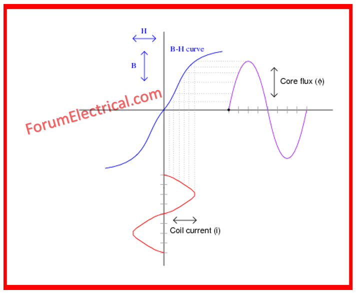
The saturated core of the transformer causes the induced voltage in the main circuit to remain relatively constant, which is the result of over fluxing.
There needs to be a lot of magnetizing current in the main circuit if the supply voltage is raised to an abnormally high value. In this magnetic state, the primary and secondary values (voltage and current) no longer have any linear relationship with one another inside the transformer core.
We don’t have over fluxing protection for sub-station transformers, so there is a chance that the high primary magnetizing current will not be adequately reflected to the secondary circuit, leading to a mismatch between the two and the operation of the differential relay.
Stipulated Withstand-Duration of Over Fluxing in Transformers
Because over fluxing protection is not usually provided in step-down transformers of substation, there must be a specified time that can be allowed in accordance with the transformer layout to withstand such over fluxing without resulting in appreciable damage to the transformer, and other protections must be sensitive enough to trip the transformer effectively within such stipulated time if the cause of over fluxing is not removed by this time.
Power transformers are intended to resist (Vn/fn x 1.1) continuously, where Vn is the typical maximum R.M.S. voltage & fn is the standard frequency.
The core design is designed so that increasing v/f results in more core loss and heating.
A transformer’s ability to endure greater v/f values, also known as the over fluxing effect, is restricted to a few minutes, as shown in the Table below.
| F = (V/f)/(Vn/fn) | 1.1 | 1.2 | 1.25 | 1.3 | 1.4 |
| Duration of the withstand restriction(in minutes) | Continuous | 2 | 1 | 0.5 | 0 |
According to the table above, when over fluxing caused by system dangers reaches the point where the factor F equals 1.4, the transformer must be tripped out of operation immediately or suffer permanent damage.
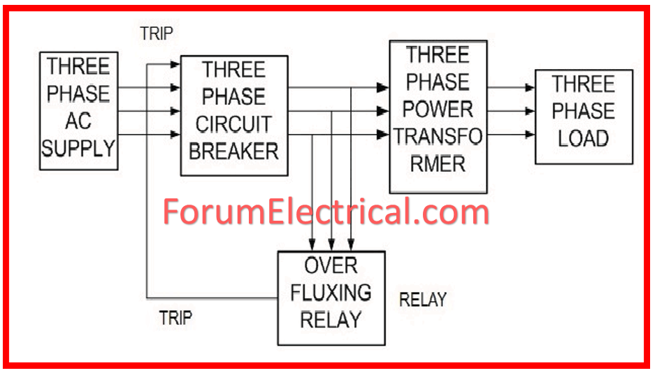
Protection against Over fluxing (v/f – Protection) in Transformer
Over-fluxing does not require high-speed tripping. Instantaneous operation is desired because it would result in tripping on momentary system disruptions that can be tolerated safely; nonetheless, the normal condition should be restored or the transformer disconnected within one or two minutes at most.
Flux density is proportional to V/f, and it is necessary to detect a V/f ratio greater than unity, where V and f are given in terms of rated quantities.
In a typical scheme designed for over-fluxing protection, the system voltage determined by the voltage transformer is subjected to a resistance to produce a proportionate current; this current, when passed via a capacitor, produces a voltage drop proportional to the function in question,
i.e. V/f
and thus to flux in the power transformer.
This is accompanied by a fixed reference DC voltage measured via a zener diode.
When the peak AC signal surpasses the DC reference, a transistor circuit activates two electro-mechanical auxiliary devices.
The initial operation is started after a predetermined time delay, whereas the second is started after an adjustable time delay.
The excess fluxing protection activates when the terminal voltage-to-frequency ratio exceeds a predefined threshold & resets when the ratio falls under 95 to 98% of operating ratio.
A potentiometer is used to calibrate the setting between 1 and 1.25 times the ratio of rated voltage to rated frequency.
The output from the first auxiliary element functions after a fixed time delay of 20 to 120 seconds, while the second output relay operates & performs the tripping function.
It has already been stated that high V/f occurs in generator, transformers & unit-auxiliary transformers when full exaltation is applied to the generator prior to reaching full synchronous speed.
V/f relay is offered in the generator’s automatic voltage regulator. This relay inhibits and prevents rising excitation current before full frequency is reached.
When connecting a V/f relay to a step-down transformer, it is better to connect it to the secondary (L.V.) of the transformer so that any changes in tap position on the H.V. are automatically handled.
Furthermore, the relay should trigger an alarm, and the operator should perform/have completed the correction action.
In extreme cases, the transformer-controlling breaker may be permitted to trip.
Why is Over Fluxing harmful for the Transformer?
Increased flux linkage causes increased eddy currents in the core, resulting in increased iron loss and core heating. This can result in irreversible core damage & short circuit failures owing to broken insulation.