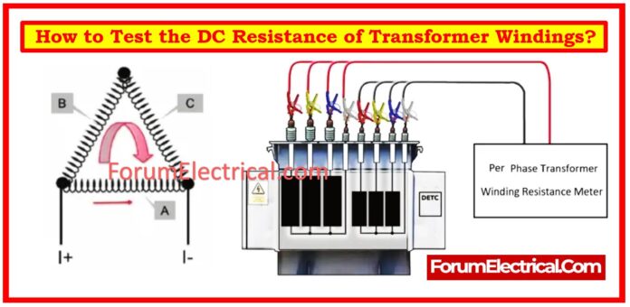
Testing the DC resistance of transformer windings is an essential step in ensuring transformer dependability and performance.
This test aids in detecting problems such as loose connections, broken windings, or manufacturing faults.
Measuring transformer winding resistance assures
- Inner wire welding,
- Lead connections, and
- Coil parameters.
It also evaluates the contact quality of tap changers & bushings.
Importance of DC Resistance Test
DC resistance testing can uncover problems such as:
- Broken strands (or) partly open circuits in windings.
- High resistance owing to faulty contacts (or) connections.
- Short circuits occur between turns in the winding.
Equipment Required
- A micro-ohmmeter (or) a similar low-resistance measurement device.
- Insulated test leads with Kelvin clips reduce lead resistance.
- Appropriate personal protection equipment (PPE).
- Temperature measurement tools (if needed for correction).
Test Preparation
- Ensure that the transformer is de-energized & disconnected from any power supplies.
- Ground the transformer to release any residual energy.
- Check that the test equipment is in proper working condition.
Test Procedure
- Connect the micro-ohmmeter.
- Connect the test leads to the appropriate winding terminals (high or low voltage). To improve accuracy, use Kelvin clips.
- Apply test current appropriate for the winding under test, as indicated by the transformer manufacturer.
- Once the current has stabilized, note the resistance value.
- Test each winding separately, including the tertiary, LV, and HV, if any are present.
Here’s a step-by-step procedure for properly doing this test:
Step 1: Measurement Points
- Measure (Delta connection) line resistances (AB & BC & CA) on a Y-connection without a neutral point and Y-connection (Star connection) with neutral point in a three-phase transformers.
- Determine phase resistances (AO & BO & CO) & neutral point resistance to a line end (e.g., AO).
- In Delta Connection, measure phase resistances at both the head & end; for closed triangle instances, measure (Delta connection) line resistances.
Step 2: Tap Changer Position
- Winding resistance in transformers with the tap changers should be measured at all tap positions.
- In On-Load Voltage (OLTC) Regulating Transformers, test the resistance of all taps in one direction and 1-2 taps in the other.
- To obtain precise measurements, ensure that the tap-changer positioning device is in correct position.
Step 3: Temperature Measurement
- Keep accurate records of winding temperature.
- For dry-type transformers, take the average surface temperature of a minimum three windings.
- For oil-immersed transformers, keep the oil temperature stable, inject transformer oil into thermometer seat & set the winding temperature to the top oil layer temperature.
- For large transformers, use the average oil temperature as winding temperature.
Step 4: Choosing the Tester
Utilize a DC resistance tester or a customized bridge that has an accuracy of at least 0.2.
Please follow these guidelines:
- Check the instrument & set the test current based on the tester manual & winding resistance size.
- Ensure every winding’s lead-out terminals are open; also, open any open delta-connected winding.
- For on-load tap changers (OLTC), restart instrument without interrupting the measuring circuit.
- When changing tap positions on non-excitation voltage-regulating transformers, turn off the power.
- For D/D (Delta-Delta) connected transformers, adjust the tap phase by phase without turning off power.
- For large capacity 5-column transformers, utilize the magnetization method to measure DC resistance and then demagnetize after testing.
- To avoid errors, wait until the winding self-inductance influence is minimized before reading data.
Before proceeding with the following step, totally discharge the measuring circuit.
Step 5: Convert Resistance
3 phase Resistance Unbalance Rate Calculation:
Resistance Unbalance Rate (%) = [(Rmax –Rmin)/Ravg] x 100
Ravg = (RA + RB + RC)/3
Where
Rmax – 3 Phase Maximum Resistance
Rmin – 3 Phase Minimum Resistance
Ravg – 3 Phase Average Resistance
RA, RB, RC – 3 Phase each Phase Resistance
Conversion Formulas:
- Ohm’s Law Calculator
- Power Loss Calculator
- Series Resistors Calculator
- Parallel Resistors Calculator
Temperature Conversion Formula:
To determine temperature-compensated resistance (Rcorrected), use the formula
Rcorrected = Rmeasured x (T2+α/T1+α)
Where
Rcorrected – Resistance at a Reference temperature (T2)
Rmeasured – Resistance at an Actual temperature (T1)
T1 – Actual Temperature (0C)
T2 – Reference Temperature (0C)
α – Temperature co-efficient of resistance for winding materials (234.5 for copper, 225 for aluminum).
Precautions While Testing
- To avoid electrical dangers, strictly adhere to all safety measures.
- Ensure that the terminals are free of moisture and impurities.
- Ensure that all connections are secure & stable.
Conclusion
DC resistance testing is important for protecting transformer health and guaranteeing continuous operation.
Following these methods will allow you to precisely evaluate the DC resistance of transformer windings, ensuring quality & dependability in transformer maintenance.
By following defined procedures, utilizing the appropriate equipment, and carefully analyzing results, you can detect possible problems early & take corrective action to extend the lifespan of the transformer.


