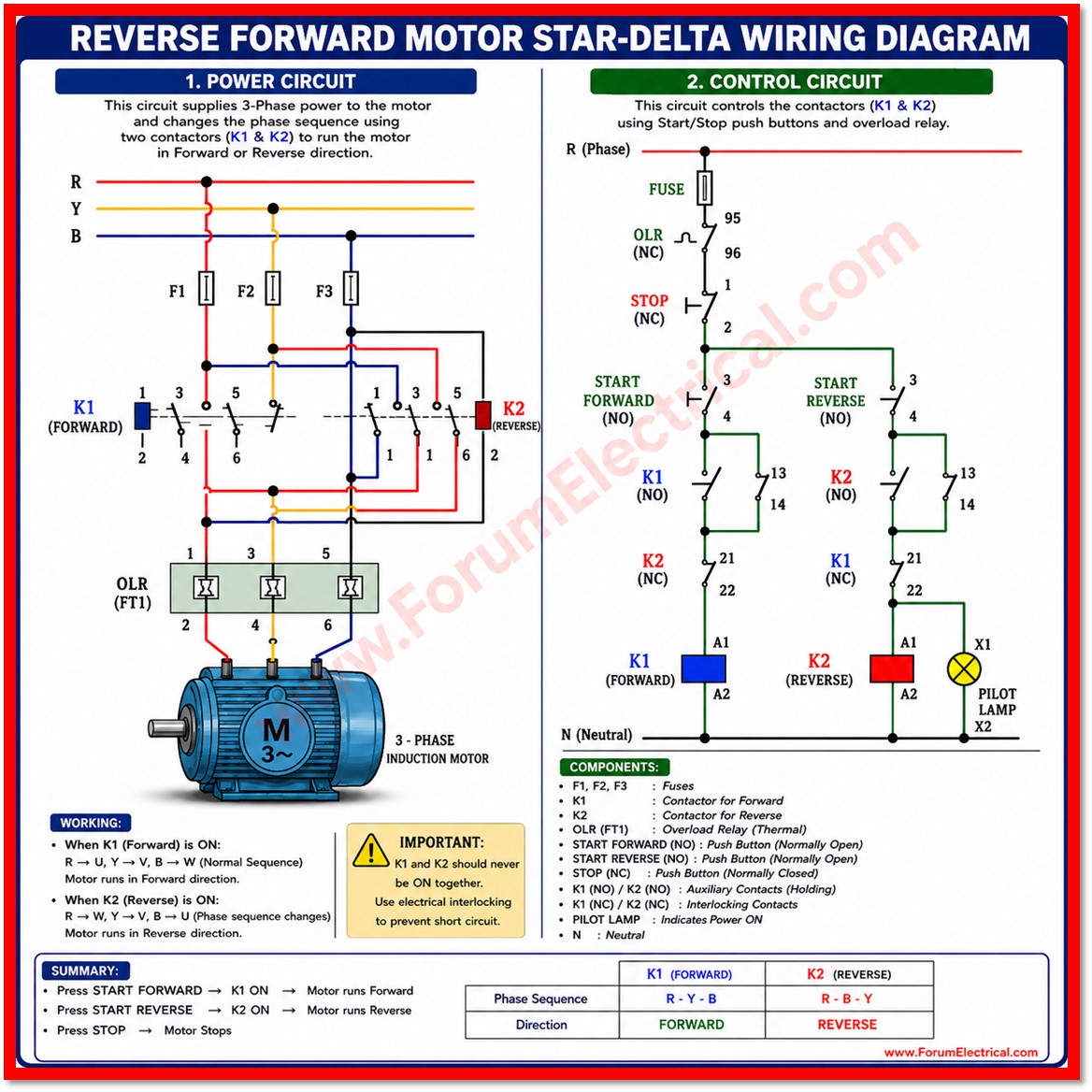
Forward-reverse motor control is one of the most fundamental and widely applied circuits in industrial automation.
It allows a three-phase induction motor to rotate in either direction on command simply by reversing the phase sequence supplied to the stator windings.
This capability is essential for equipment that must move loads back and forth, raise and lower loads (or) reposition a mechanism without operator intervention on the supply wiring.
A forward-reverse starter is built from 2 power contactors:
- Overload relay and
- Control circuit
that includes push buttons, holding (sealing) contacts and electrical interlocks.
This post explains the complete working principle, the power and control circuit wiring, the function of every component, protective interlocking methods and best practices for safe commissioning.
Principle of Direction Reversal
A three phase induction motor direction of rotation is determined by the phase sequence applied to its stator terminals commonly labelled U, V and W.
Under a standard sequence such as R-Y-B, the rotor turns in one direction. If any two of the three supply lines are interchanged while the third remains unchanged the resulting phase sequence reverses and the rotating magnetic field in the stator reverses direction with it.
The rotor which follows the rotating field therefore reverses its direction of rotation as well.
In a forward-reverse starter, this line-swapping is achieved automatically through 2 separate contactors:
- one wired for the forward sequence and
- one wired with two of its output lines transposed for the reverse sequence.
The operator never touches the power wiring directly; selecting forward or reverse is done entirely through low-voltage push button control.
Main Components
| Component | Function |
|---|---|
| MCCB / MCB | Main incoming isolator and short-circuit protection for the power circuit. |
| Contactor K1 (Forward) | Connects supply to the motor in the normal R-Y-B sequence for forward rotation. |
| Contactor K2 (Reverse) | Connects supply to the motor with two lines interchanged for reverse rotation. |
| Overload Relay (OLR) | Monitors motor current and trips the control circuit on sustained overload, protecting the winding from thermal damage. |
| Start Forward PB (NO) | Momentary push button that energizes K1. |
| Start Reverse PB (NO) | Momentary push button that energizes K2. |
| Stop PB (NC) | Common push button that de-energizes whichever contactor is running. |
| Auxiliary Contacts (13-14 NO) | Holding / sealing contacts that latch the contactor coil after the start button is released. |
| Auxiliary Contacts (21-22 NC) | Electrical interlock contacts that block the opposite contactor from energizing. |
Power Circuit Wiring
The power circuit carries the full-load current from the three-phase supply to the motor terminals. Both contactors, K1 and K2 that take their supply from the same incoming MCCB and both feed the same overload relay before the motor terminals U, V and W.
- The three incoming lines (R, Y, B) are connected to the top (line side) terminals of both K1 and K2 in parallel.
- On the output side of K1, the lines are wired straight through in sequence: R→U, Y→V, B→W. This generates forward rotation.
- On the output side of K2, two lines are deliberately transposed: R→W, Y→V, B→U (only two lines need to be swapped; the third stays in place). This generates reverse rotation.
- The outputs of K1 & K2 are joined on the load side and routed through the overload relay to the motor terminals U, V, W.
- The overload relay bimetallic sensing elements are inserted in series with all 3 motor phases so that an overcurrent in any phase is detected.
Because K1 and K2 output terminals are effectively tied together at the motor, it is absolutely essential that K1 and K2 are never allowed to close at the same time.
If both closed together, the transposed lines of K2 would create a direct line-to-line short circuit across the supply.
This hazard is the entire reason electrical interlocking exists and it is also discussed below in detail.
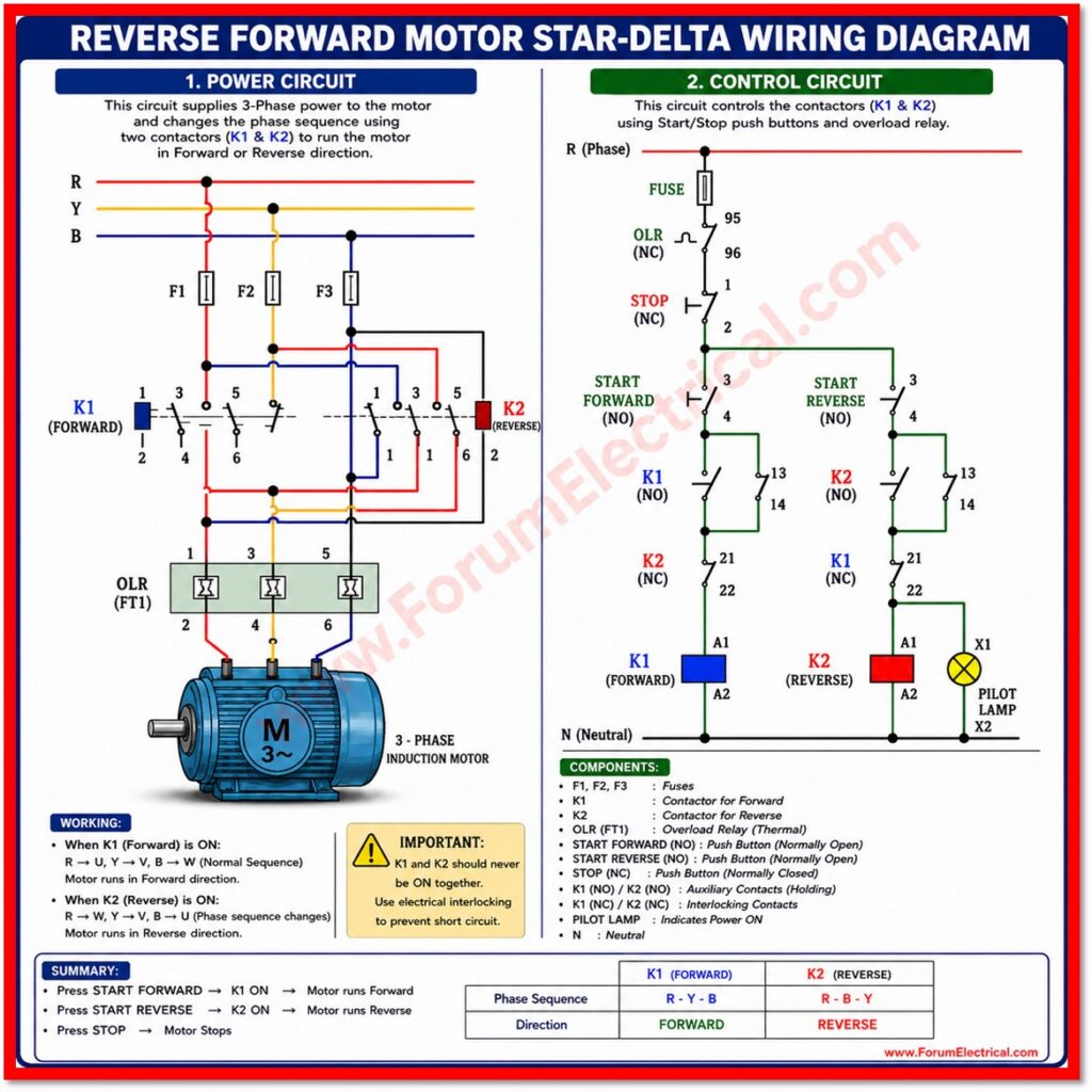
Control Circuit Wiring
The control circuit operates at the coil voltage of the contactors (commonly 230V AC (or) 24V DC per the coil rating) and is protected by a separate control fuse (or) MCB fed from two of the incoming phases (or) from a control transformer.
- Forward branch: Start-Forward PB (NO) in parallel with K1 own 13-14 holding contact, feeding K1 coil through K2 own 21-22 normally closed interlock contact.
- Reverse branch: Start-Reverse PB (NO) in parallel with K2 own 13-14 holding contact and feeding K2 coil through K1 own 21-22 normally closed interlock contact.
When the Start-Forward button is pressed current flows through K2 closed 21-22 interlock into the K1 coil, energizing it. K1 own 13-14 auxiliary contact closes in parallel with the push button, holding the coil energized after the button is released. At the same time, K1 owns 21-22 contact (wired into the reverse branch) and physically avoids K2 from being energized until K1 drops out.
Electrical Interlocking for Safety
Electrical interlocking is the safety mechanism that prevents K1 and K2 from ever being closed together.
It is implemented using the normally closed (21-22) auxiliary contact carried on each contactor:
- K1s NC auxiliary contact is wired in series with K2s coil circuit.
- K2s NC auxiliary contact is wired in series with K1s coil circuit.
Many industrial panels add a second layer of protection called mechanical interlocking, in which a physical lever (or) linkage between the two contactor bodies makes it impossible for both armatures to close at once even under a welded contact fault.
Where personnel safety (or) high value equipment is involved, using both electrical and mechanical interlocking together is considered best practice.
Some designs also wire the opposite start push button as an additional interlock, using its normally closed contact in series with the running contactor’s coil circuit.
This allows an operator to press Start-Reverse directly while Forward is running: the NC contact on the Reverse button first drops out K1 and then once K1s own NC interlock contact recloses and K2 can pick up. This is known as a direct reversal (or) plugging-capable circuit and must only be used where the mechanical system and motor are rated for sudden direction reversal.
Sequence of Operation
- Close the main MCCB to energize the power and control circuits.
- Press Start-Forward: K1 coil energizes, K1 main contacts close, K1 holding contact seals the circuit, K1 interlock contact opens to lock out K2. The motor runs forward.
- Press Stop: control supply is broken, K1 de-energizes, motor coasts to a stop, and both interlock paths are released.
- Press Start-Reverse: K2 coil energizes, K2 main contacts close with two lines transposed, K2 holding contact seals the circuit, K2 interlock contact opens to lock out K1. The motor runs reverse.
- If an overload occurs at any time, the OLR trip contact opens the common control line, dropping out whichever contactor is running and sounding or indicating a fault as configured.
Typical Applications
Forward-reverse starters of this type are used wherever a motor should drive a mechanism in 2 directions under push-button or automatic control, including:
- Belt and roller conveyors require reversible material flow.
- Hoists, winches and cranes for raising and lowering loads.
- Rolling shutters and motorized gates.
- Machine tool feed drives and positioning tables.
- Mixers, agitators, and augers requiring bidirectional operation.
Commissioning and Safety Checklist
Before energizing a forward-reverse starter for the first time verify the following:
- Confirm the phase sequence and that K2s output wiring has exactly two lines transposed relative to K1 not all three.
- Torque-check all power and control terminals; loose connections are a leading cause of nuisance tripping and contact burning.
- Set the overload relay to the motors rated full load current (FLC) referencing the motor nameplate.
- Verify that the 21-22 interlock contacts are wired correctly by testing that Start-Reverse has no effect while Forward is running and vice versa.
- Bump-test each direction briefly at no load to confirm correct rotation before coupling the load.
- Inspect mechanical interlock linkages, if fitted, for free movement and correct alignment.
Conclusion
The forward-reverse starter is a compact and reliable way to give a three-phase induction motor bidirectional control using only two contactors, an overload relay, and a small set of push buttons.
Its safety depends entirely on correct interlocking: the 13-14 holding contacts keep each contactor latched after the push button is released while the 21-22 interlock contacts guarantee that the two contactors can never close together and short the supply.
Understanding both the power circuit’s line-transposition logic and the control circuit’s interlocking logic is essential for anyone installing, maintaining (or) troubleshooting this widely used industrial control scheme.

