
Insulation resilience coordination in power systems was developed to coordinate the electrical insulation levels of various electrical power system components, including the transmission network, in a way that, in instances that an insulator fails, the system is least damaged, is easiest to repair and replace, and causes the least amount of disruption to the power supply.
Any time an electrical power system experiences an overvoltage, there is a danger that its insulating system could fail.
The poorest insulation point closest to the overvoltage source has a significant failure probability. All equipment and parts in the power system & transmission networks are equipped with insulation.
Compared to other places, certain insulators are simple to replace and maintain. In some places, insulation is difficult to replace and repair, and doing so could be very expensive and necessitate a lengthy power outage.
Additionally, insulator failure at these locations may render a larger portion of the electrical network inoperable. Therefore, it is preferable that only those easily replaceable & repairable insulators fail in an insulator failure condition.
The primary objective of insulation resilience coordination is to bring the expense and disruption brought on by insulation failure down to a level that is both financially feasible and operationally manageable.
In the insulation coordination methodology, the insulation of the different system components must be graded in such a way that, should flash over occur, it must do so at the desired locations.
To effectively recognize insulation coordination, it is necessary to first comprehend several fundamental terms used in the power system.
Let’s discuss in this post.
Fundamental Terms in Electrical Power System
1). Nominal System Voltage
The phase-to-phase voltage of a system, for which it is typically constructed, is known as the nominal system voltage such as 11KV, 33KV, 110KV, 220KV, and 400KV.
2). Maximum System Voltage
Maximum system voltage is the highest permitted power frequency voltage that could occur for a longer period of time when the power system is under low or no load. Additionally, it is phase-to-phase measured.
The following is a list of several nominal system voltages and their associated maximum system voltages for the reference.
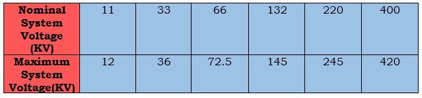
NOTE: As can be seen from the table above, the maximum system voltage is often set at 110% of the matching nominal system voltage up to the voltage level of 220 kilovolts. However, if go above 400 kilovolts, the maximum system voltage drops to 105%.
3). Earthing Factor
This is the ratio between the rms phase to phase power frequency voltage that would have been attained at the selected location in the absence of the fault and the greatest rms phase to earth power frequency voltage during a sound phase during the fault.
The earthing conditions of a system as seen from the chosen fault point are generally characterized by this ratio.
4). Effectively Earthed System
If the earthing factor does not exceed 80%, a system is considered to be effectively earthed, and if it does, it is not. For an isolated neutral system, the factor of earthing is 100%, but for a system that is strongly earthed, it is 57.7% (1/√3 = 0.577).
5). Insulation Level
Throughout the course of its lifespan, each component of electrical equipment is subjected to a variety of aberrant transient over voltage conditions.
Equipment reliability may also be affected by transient power frequency over-voltages and/or lightning surges.
The insulation level of a high voltage power system is established by calculating the maximum impulse voltages & short duration power frequency over voltages that a single component of the system can withstand.
For systems with ratings lower than 300 kilovolts, insulation thickness is calculated by factoring in the voltages required to survive a lightning impulse and a short-term power frequency.
The switching impulse withstand voltage & the short duration of the power frequency withstand voltage are taken into consideration for equipment having a rating greater than or equal to 300KV.
6). Lightning Impulse Voltage
There are three distinct wave forms that can be used to depict the disruptions in the system caused by lightning.
- A 1.2/50 wave is that happens to the voltage of a lightning impulse as it travels through a transmission line before reaching an insulator.
- If the lightning disturbance wave travels through an insulator and creates a flash over, the wave will be shaped like a chopped wave.
- As the lightning impulse voltage rises until it is alleviated by flash over, the voltage across the insulator can suddenly and very steeply drop if the lightning strike is directed towards the insulator.
The duration and forms of all 3 of these waves are very distinct from one another.
7). Switching Impulse
Unipolar voltage may arise in the system during switching operations. It’s possible that the wave’s form is periodic damping or oscillation. An alternating impulse wave features a sharp leading edge and a long, damped oscillating tail.
8). Short Duration Power Frequency Withstand Voltage
A component of electrical equipment must be able to tolerate a specified rms value of the sinusoidal power frequency voltage for a limited amount of time, usually 60 seconds.
9). Protection Level Voltage of Protective Device
- Surge arrestors and
- Lightning arrestors
are examples of over voltage protective devices; they are designed to resist a particular amount of transient over voltage before dissipating the excess energy to the ground.
There will be no overvoltage spikes higher than that. When switching impulses or lightning impulses are applied to the terminals of an over voltage protective device, that device’s protection level is the maximum peak voltage value that should not be exceeded.
Insulating Coordination Methods
Let’s analyse into each of the insulating coordination methods:
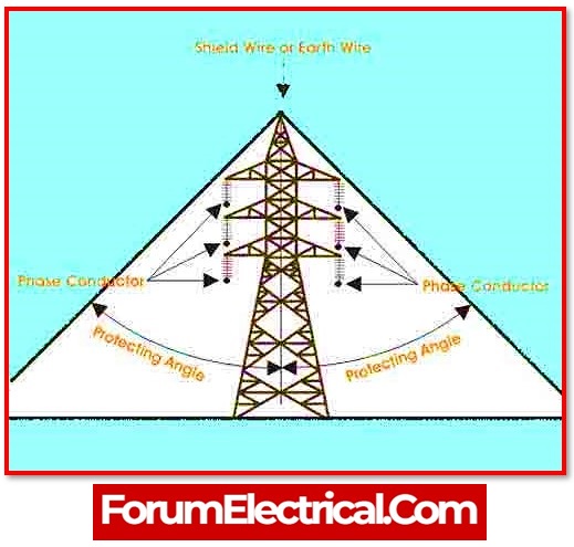
1). Using an Earth or Shield Wire
Overhead transmission lines can experience a surge from lightning if the bolts strike them directly. A shield wire (or) earth wire, installed at a safe distance from the transmission line’s top conductor, can provide necessary protection.
All of the conductors can be shielded from direct lightning strikes if the shield wire is securely fastened to the transmission tower body & the tower is effectively earthed.
To protect the electrical substation’s many components from potential lightning strikes, an earth wire, ground wire, or shield wire is connected high above it.
2). Coordination of Insulation Using the Conventional Method
There are two types of transient voltage stressors that can affect the electrical power system’s components:
- Switching impulse voltage and
- Lightning impulse voltage.
Including a protective device, such as a lightning arrestor, can reduce the peak magnitude of transient over voltages that reach the components.
In a perfect environment, there would be no risk of insulation breakdown in any part of the power system so long as kept the insulation level of all the components above the threshold of protection provided by the protective device.
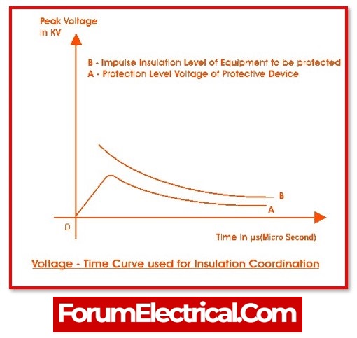
As the transient overvoltage crosses the surge protectors, it will have an amplitude equal to the protection level voltage, and the impulse insulation level of the components will be lower than the protection level voltage.
The impulse insulation level is typically set 15–25% over the protective level voltage of the devices providing that level of protection.
3). Coordination of Insulation Using Statistical Methods
The length of the insulator strings & the clearance in air increase approximatively to 1.6 as the transmission voltage increases. Below, the necessary number of insulator discs in a suspension string at various over voltages.
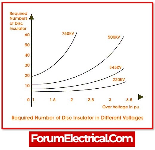
When comparing the 220KV and 750KV systems, it can be noted that the increase in discs is very small for the 220KV system due to the rise in the over voltage factor from 2 to 3.5.
Protecting lower voltage lines up to, for example, an over voltage factor of 3.5 (say) may be economically possible, but protecting higher voltage lines upto to an over voltage factor of in excess of roughly 2 to 2.5 .
Changing voltages is the primary objective of higher voltage systems. However, with well-planned switching devices, even these can be managed.
