")
What is an Insulation Resistance IR test?
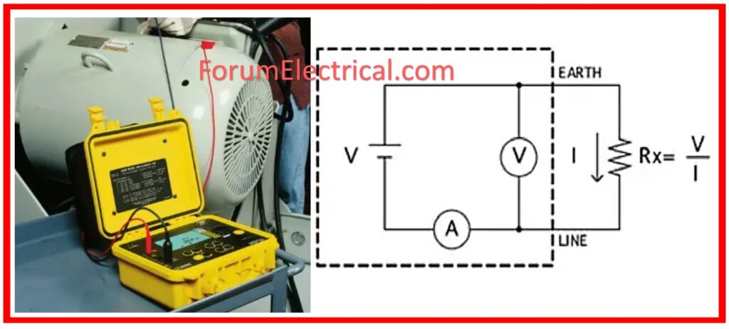
Insulation resistance, often known as IR, is a measurement that determines how good (or) bad your insulation is. This test can assist you in obtaining a comprehensive understanding of the condition of your electrical equipment.
The Insulation Resistance Test (IR Test) consists of physically evaluating the equipment, isolating it from adjacent circuits, & connecting an insulation tester set to voltages corresponding to the equipment’s rating to determine insulation resistance over time.
Readings are taken at different time intervals & compared to standards to determine whether the insulation state is harmful, or good.
Maintaining insulation resistance records enables for the comparison of values over time in order to evaluate equipment health.
The post outlines how to perform an insulating resistance test on electrical equipment to assess if it is in good working order and predict future deterioration.
Scope
To determine if equipment is in good condition for its intended use and predict if deterioration is likely to occur, potentially leading to a shorter lifespan.
These results can be preserved as a record for future comparison and understanding of insulation variations throughout maintenance.
Equipment Required
- Insulation tester (5000V DC)
Test Procedure
Before starting testing, take the following precautions:
- Visually examine the component for dust and moisture.
- Make sure the component has been separated from other connected systems to avoid potential feedback to other components (or) circuits not being tested.
- Check the ground for component under test, connect test equipment to system ground, and isolate lightning arrestors, capacitors, and VT/control transformers.
Insulation Test
- Connect insulation tester leads to one phase conductor & earth.
- The test voltage must be selected in accordance with table.
- The length could range from 1 to 10 minutes, with the reading obtained at the end of that time.
- Prior to disconnecting the test leads, the test object must be discharged through the earth.
- The similar method will be followed for the next phases.
| Rated Voltage | Test Voltage |
| 100-1000 V AC/DC | 1000 V DC |
| >1000 to <5000 V AC | 2500 V DC |
| > 5000 V AC | 5000 V DC |
Influencing Factors
Insulation resistance is affected by temperature, humidity, & moisture. The ambient temperature should be recorded during the test.
Temperature and insulating resistance are inversely proportional.
Test Methods
1). Short Time (Or) Spot Reading
- Connect the megger instrument to the insulation to be evaluated and apply for 60 seconds.
- The reading is taken at the conclusion of that time.
2). Time Resistance Method
- Time resistance method, which is temperature-independent, provides more information on insulation than spot measurements.
- The test voltage is applied for 10 minutes, with readings obtained every 15 seconds for the first minute & every minute for the next 10 minutes. So, a Megger equipment will assist with this test easier & provide the best results.
- The dielectric absorption factor and polarization index can be calculated as shown below:
- Dielectric Absorption Factor = 60 (sec) reading/ 30 (sec) reading
- Polarization Index = 10 (min) reading / 1(min) reading
| Insulation Condition | 10min/1min Ratio(Polarisation Index) |
| Dangerous | <1 |
| Poor | >1 to <1.5 |
| Questionable | >1.5 to <2 |
| Good | >2 to <4 |
| Excellent | >4 |
3). Step Voltage (or) Multi- Voltage Method
- This method requires a multi voltage megger instrument, preferably with 1:5 voltage ratio ranges.
- Any reduction of insulation resistance at higher voltage is a sign of an insulation weakness.
This IEEE 43-2000 covers the preferred method for evaluating insulation resistance of armature & field windings in rotating machines.

Acceptable Limits
The value of the insulating resistance should ideally be equal to the minimum specified by the manufacturer.
In case that this value is not accessible, the component that is being evaluated ought to have a minimum of one megaohm each for every one thousand volts of rated voltage, in addition to an additional megaohm.
Why are Insulation Resistance Tests performed?
Insulation starts breaking down as soon as it is manufactured. Its insulating properties degrade with aging.
Any severe installation environment, particularly one with temperature fluctuations and/or chemical pollution, hastens this process.
Stress is caused by a variety of circumstances, including:
- Electrical stresses are mostly related to overvoltage & undervoltage.
- Frequent start-up & shutdown procedures might result in mechanical stress.
- Balancing issues with rotating machinery, as well as any direct load on cables and systems in general.
- In general, the presence of chemicals, oils, corrosive vapours, and dust has an impact on the insulating performance of materials.
- Stresses associated with temperature variations: When paired with mechanical stresses induced by start-up and shutdown cycles, expansion & contraction stresses have an impact on the characteristics of insulating materials. Extreme temperatures cause materials to age.
- Environmental pollution accelerates the aging of insulation.
")


, including its purpose, process, and importance in electrical maintenance. Learn how Insulation Resistance testing maintains the safety and reliability of electrical equipment by assessing insulation health using Megger.)