
If the motor is not turned on right away, it must be protected against external influences such as moisture, high temperatures, and contaminants to avoid damages to the insulation. Before putting the motor back into service after a long period of storage, the winding insulation resistance must be measured.
Thumb Rule
As a general thumb rule, ten Megaohm (10 MΩ) or more is required.
| Insulation Resistance (IR) Value | Insulation Level |
| 2 MΩ or less | Bad |
| 2-5 MΩ | Critical |
| 5-10 MΩ | Abnormal |
| 10-50 MΩ | Good |
| 50-100 MΩ | Very good |
| 100 MΩ | Excellent |
A megohmmeter, often known as a high resistance range ohmmeter, is used to measure insulation resistance.
The test operates as follows: a DC voltage of 500 V (or) 1000 V is supplied between the motor’s windings and ground.
In this regard, it is important to note three points:
- Insulation Resistance
- Measurement and
- Checking.
Insulation Resistance
The minimum insulation resistance of a new, cleaned, (or) repaired windings to ground is 10 (MΩ) Megohm (or) greater.
The minimal insulation resistance, R, is derived by multiplying the rated voltage by the constant value 0.5 Megohm/kV.
Ex:If the rated voltage is 690 V = 0.69 kV, then,
Minimal Insulation Resistance = 0.69 kV x 0.5 Megohm/kV
= 0.35 Megohm
Measurement
500 V DC is used to measure the winding’s minimum insulation resistance to ground. It is recommended to wind at 25°C ± 15°C.
Depending on the type and efficiency of the motor, the maximum insulation resistance must be measured at 500 V DC with the windings at an operating temperature of 80 to 120°C.
Checking
A new, cleaned (or) repaired motor that have been stored for a while may have humid windings that need to be dried if its insulation resistance is less than 10 Mohm (MΩ).
An extended running duration of the motor may cause the minimum insulating resistance to fall to a critical value. The motor can operate as long as the measured value is higher than the determined value of minimum insulation resistance.
To prevent injuries from the high leakage voltage, the motor must be stopped right away if it falls below this threshold.
The purpose of the IR test results is to provide information about the quality of the entire material used as insulation, rather than to identify specific flaws in the insulation as might be the case with an actual HIPOT test.
Many wire & cable manufacturers utilize the insulation resistance test to monitor their insulation manufacturing processes and identify emerging issues before process parameters drift outside of permitted limits, even when it is not required by the user.
IR Testers Selection (Megger)
There are various insulation testers that can test at 500, 1000, 2500, and 5000 V. The following are the insulation testers’ suggested ratings:
| Level of Voltage | IR Tester |
| 650V | 500V DC |
| 1.1KV | 1KV DC |
| 3.3KV | 2.5KV DC |
| 66KV and Above | 5KV DC |
Meggering – Test Voltage
Test Voltage (AC) = (2x Name Plate Voltage) + 1000
is the general rule of thumb when using AC voltage.
Test Voltage (DC) = (2x Name Plate Voltage)
is the general rule of thumb when using DC voltage (In all Megger).
| Cable/ Equipment Rating | DC Test Voltage |
| 24V To 50V | 50V To 100V |
| 50V To 100V | 100V To 250V |
| 100V To 240V | 250V To 500V |
| 440V To 550V | 500V To 1000V |
| 2400V | 1000V To 2500V |
| 4100V | 1000V To 5000V |
Megger’s Measurement Range
| Test Voltage | Measurement Range |
| 250V DC | 0MΩ To 250GΩ |
| 500V DC | 0MΩ To 500GΩ |
| 1KV DC | 0MΩ To 1TΩ |
| 2.5KV DC | 0MΩ To 2.5TΩ |
| 5KV DC | 0MΩ To 5TΩ |
Meggering Precautions
Before Meggering
Check that test circuit all connections are tight. Before using the megger, make sure it displays INFINITY when not attached & ZERO once the 2 terminals are connected & the handle is rotated.
During Meggering
When checking for earth, be sure the conductor far end is not contacting; otherwise, the test will indicate bad insulation when it is not.
Check that the earth used for testing for earth & open circuits is a good one; otherwise, the test will result in incorrect results. Spare conductors are not to be meggered while other working conductors of same cable are attached to the relevant circuits.
After Meggering (Cable Completion)
- Check that all conductors have been properly correctly reconnected.
- Check the functionalities of the points, tracks, and signals connected via the cable for proper response.
- In the case of signals, the aspect must be verified directly.
- In the event of points, verify positions. Check to see whether any polarity of the feed taken across the cable has been mistakenly earthed.
Meggering Safety Requirements
- All equipment undergoing test must be unplugged and separated.
- To ensure the safety of the person conducting the test, the equipment must be discharged (shunted or shortened out) for at least the duration of the test voltage.
- Never employ Megger in a highly explosive environment.
- To ensure safety, ensure that all switches are to be blocked and cable ends are correctly marked.
- Isolated cable ends must be separated from the supply and shielded from contact with the supply, ground, (or) accidental contact.
- The installation of safety barriers with the warning signs, as well as an open communication route between testing professionals.
- When the humidity level exceeds 70%, do not megger.
- Megger reading rises first, then remains constant, indicating good insulation.
- Megger reading rises first, then falls due to poor insulation.
- The expected IR value is 20 to 30 degrees Celsius.
- If the temperature drops by 10 degrees Celsius, the IR levels increase by double.
- If the previously mentioned temperature is raised by 70 degrees Celsius, the IR values decrease by 700 times.
Megger: How to Use It?
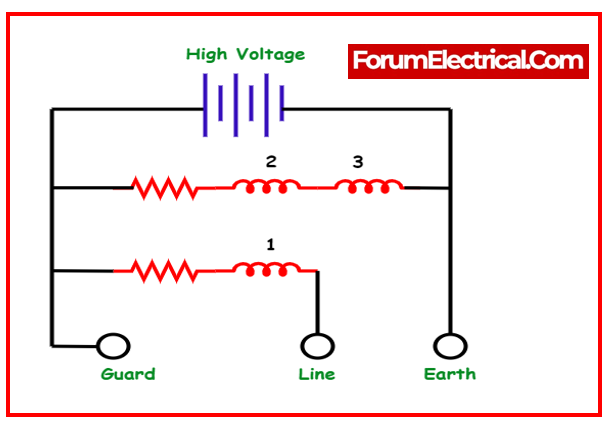
Meggers has three connecting points:
- Line Terminal (L),
- Earth Terminal (E), and
- Guard Terminal (G).
Resistance is determined between the Line & Earth terminals, through which electricity will flow through coil 1. The “Guard” terminal is available for use in particular testing conditions in which one resistance needs to be isolated from the another.
Consider the following condition:
The insulation resistance of a two-wire cable needs to be examined.
To determine the insulation resistance from the conductor to the outside of the cable, connect the megger’s “Line” lead to one of the conductors and the megger’s “Earth” lead to a wire wrapped around the cable’s sheath.
Configuration of a Megger
The resistance between the one conductor & the outside sheath should be read by the Megger in this configuration.
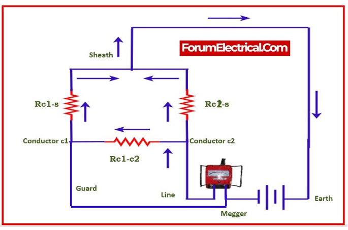
We want to measure resistance between conductor-2 and sheaths, but the megger really measures resistance in the parallel connection with the series combination of the conductor-to-conductor resistance (Rc1-c2) & first conductor to sheath resistance (Rc1-s).
If we have no concern about this, we can continue with the test as scheduled. If we simply want to measure the resistance between the 2nd conductor & the sheath (Rc2-s), we must use the “Guard” terminal on the megger.

When the “Guard” terminal is connected to the first conductor, the two conductors are nearly equal in potential.
When there is a small voltage between them, the insulating resistance is virtually infinite, and hence no current flows between the two conductors.
As a result, the Megger’s resistance indication will be solely based on the current leaking through the second conductor’s insulation, the cable sheath, and the wire wrapped around, rather than the current leaking via the first conductor’s insulation.
The guard terminal (if present) functions as a shunt, removing the linked element out of the measurement. In other words, it enables to evaluate certain components of an enormous component of electrical equipment selectively.
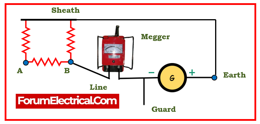
Consider a two-core cable with the sheath as an example.
There are 3 resistances to consider, as seen in the diagram below.
If we take a measurement between core B and the sheath without connecting to the guard terminal, some current will flow from B to A & from A to the sheath. Our standard would be low. By attaching the guard terminal to A, the two cable cores will be at almost the same voltage, removing the shunting effect.
RTOTAL = (RLX 2RL) / (RL + 2RL) = 2RL2 / 3RL = (2/3) RL
According to the preceding formula, if the coil resistance is 20 Ω,
the resistance measured by the ohmmeter will be
2/3 x 20 (or) 0.66 x 20 = 13.3 Ω
Once again, the coils can be measured directly into the motor’s electrical box (or) on the motor protection in an electrical cabinet. Simply ensure that there is no power in cabinet.
Summary
In order to ensure that the motor receives the same amount of power, it is necessary to match the resistance between all three leads.
There must be no connection at all (infinite resistance) between the ground and the leads at any point in an electrical circuit.
The resistance that is measured must be equal to two-thirds of the coil resistance.