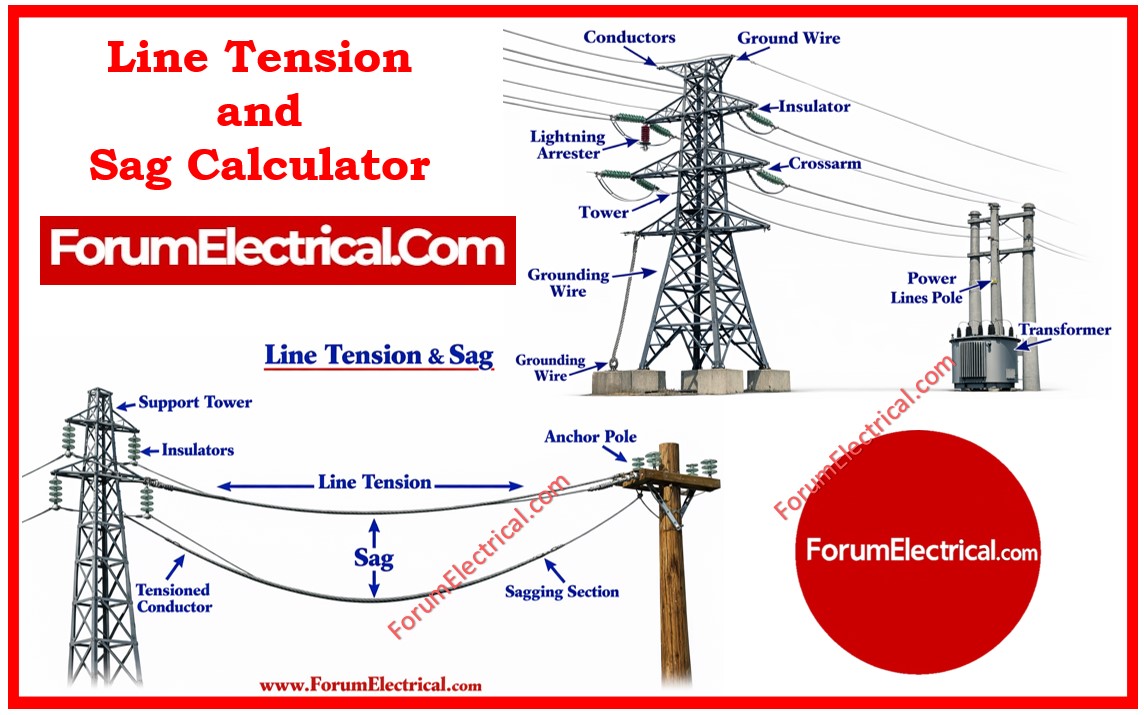
The Line Tension & Sag Calculator is an online calculator tool designed for power utility professionals, electrical engineers and transmission line designers.
Calculator
⚡ Line Tension & Sag Calculator
Overhead Transmission & Distribution Engineering
IEEE / IS 802 Standards ReferenceClick here for more Electrical Calculators
You can also follow us on Facebook and Linkedin to receive daily updates.
It calculates
- Sag,
- Tension,
- Wind & ice loading and
- Ground clearance
for overhead conductors in accordance with IEEE and IS 802 standards.
Accurate sag and tension calculations are very important for ensuring
- Safe conductor clearances,
- Mechanical integrity of tower structures and
- Compliance with statutory requirements.
Calculate the sagging transmission lines and tension accurately to make sure a safe conductor clearance, optimal mechanical strength and reliable power system performance under a varying load & weather conditions.
This online calculator tool that can withstand both level and inclined spans, incorporating thermal effects, wind loading and ice accretion.
What is Sag?
Sag is defined as the distance across the highest point of electric poles (or) towers and the lowest point of a conductor that is connected between 2 poles (or) towers.
Span Length
It is the shortest distance between 2 towers (or) poles.
Sag S = (WL2)/ (8T)
Where
S – Sag of the conductor
W – Weight of the conductor
I – Span length of the conductor
T – Working tension on the conductor
Input Parameters
Span & Tower Parameters
| Parameter | Symbol | Unit | Description |
|---|---|---|---|
| Span Length | S | metres (m) | Horizontal distance between towers |
| Tower 1 Height | h₁ | metres (m) | Attachment point height at tower 1 |
| Tower 2 Height | h₂ | metres (m) | Attachment point height at tower 2 |
Conductor Parameters
Supported conductor presets:
- ACSR: Aluminium Conductor Steel Reinforced
- AAC: All Aluminium Conductor
- AAAC: All Aluminium Alloy Conductor
- HDC: Hard Drawn Copper
| Parameter | Symbol | Unit | Notes |
|---|---|---|---|
| Weight per metre | w | kg/m | Self-weight of conductor |
| Cross-section Area | A | mm² | Electrical & mechanical sizing |
| Outer Diameter | d | mm | Used for wind & ice load calculation |
| Ultimate Tensile Strength | UTS | N | Breaking load from manufacturer |
| Safety Factor | FOS | dimensionless | Typically 2.0 for HT lines |
| Modulus of Elasticity | E | N/mm² | ACSR ≈ 65,000 N/mm² |
| Thermal Expansion Coeff. | α | ×10⁻⁶ /°C | ACSR ≈ 19.3 × 10⁻⁶ /°C |
Wind & Ice Loading
| Parameter | Symbol | Unit | Notes |
|---|---|---|---|
| Wind Pressure | P | N/m² (Pa) | Per IS 802 wind zone map |
| Ice Radial Thickness | t | mm | Enter 0 if no ice loading |
Temperature Parameters
| Parameter | Symbol | Unit | Notes |
|---|---|---|---|
| Erection Temperature | T₀ | °C | Temperature at time of stringing |
| Operating Temperature | T | °C | Maximum design temperature |
Calculation Methodology
Maximum Allowable Tension
The maximum horizontal tension H is derived by applying the safety factor to the conductors UTS:
H = UTS ÷ FOS
Loading Calculations
Conductor self-weight (N/m)
wc = w x g = w x 9.81
Ice load per unit length (N/m)
wice = 900 x π x t x (d + t) x 9.81
Wind load per unit length (N/m)
Fw = P x (d + 2t)
Total resultant load (N/m)
wt = √(wvert² + Fw²)
Sag Calculation
Sag for a level span
Sag = wt x S² ÷ (8 x H)
For uneven spans (inclined), the point of maximum sag x₁ from tower 1
x₁ = S/2 – (Δh x H) ÷ (wt x S)
Sagmax = wt x x₁² ÷ (2 x H)
Catenary Constant
a = H / wt
The catenary constant a (in metres) indicates the “stiffness” of the catenary. A larger value means lower sag relative to span length.
Output Results
| Output | Unit | Description |
|---|---|---|
| Max allowable tension (H) | N | Horizontal tension at midspan |
| Sag – level span | m | Sag assuming equal tower heights |
| Max vertical sag (uneven) | m | Sag at point x₁ for inclined span |
| Wind load per metre (Fw) | N/m | Transverse wind force per unit length |
| Total resultant load (wt) | N/m | Combined vertical & wind loading |
| Slant distance (L) | m | Straight-line distance between supports |
| Height difference (Δh) | m | Vertical offset between tower attachment points |
| Catenary constant (a = H/wt) | m | Catenary parameter |
| Max sag point from tower 1 | m | Horizontal position of lowest conductor point |
| Ground clearance status | – | OK (or) warning based on minimum clearance check |
Conductor Preset Data
| Conductor Type | Weight (kg/m) | Diameter (mm) | Elasticity E (N/mm²) | α (×10⁻⁶/°C) |
|---|---|---|---|---|
| ACSR | 1.592 | 18.6 | 65,000 | 19.3 |
| AAC | 1.35 | 17.2 | 58,000 | 23.0 |
| AAAC | 1.28 | 16.8 | 69,000 | 23.0 |
| HDC (Copper) | 2.10 | 17.5 | 120,000 | 17.0 |
Standards & Compliance Reference
IS 802 (Part 1/Sec 1):1995: Indian Standard for overhead transmission line towers, loads and permissible stresses.
IS 802 (Part 1/Sec 2):1992: Material, fabrication and erection of overhead lines.
IEEE Std 524-2003: IEEE Guide to the Installation of Overhead Transmission Line Conductors.
IEC 60826: Design criteria for overhead transmission lines.
IS 398 (Parts 1–5): Aluminium conductors for overhead power transmission.

