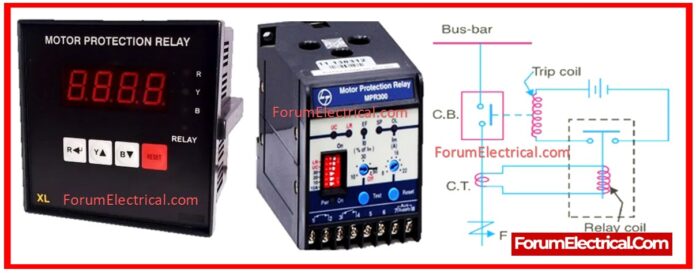
Low Tension (LT) protection relays protect electrical systems by finding abnormal conditions such as
- Safety Precautions
- Equipments Required
- General Relay Testing Procedure
- Visual Inspection
- Functional Testing
- Secondary Injection Testing
- Overcurrent Protection Test
- Earth Fault Protection Test
- Under/Over Voltage Test
- Phase Failure/Unbalance Test
- Contact Output Verification
- Reset Test
- Insulation Resistance Test
- Post-Test Procedure
- Documentation
- Overloads,
- Short circuits, and
- Ground faults.
Periodic testing ensures that they perform properly.
Nowadays, digital protection relays are mostly used. If we want to evaluate health performance, we must do relay tests.
The first relay performance test is performed after commissioning, followed by relay testing according to a yearly time plan.
Pre-set value (or) protection relays are validated or tested using test equipment. All protective relays are also subject to maintenance activity.
All connections have been checked and cleaned thoroughly.
Safety Precautions
- Ensure that the circuit is de-energized & separated.
- Display warning signs.
- Wear PPE (gloves, glasses, and insulated tools).
- Make sure all testing equipment is properly calibrated.
Equipments Required
- Multimeter
- Insulation Resistance Tester
- Secondary Injection Test Kit/Relay Test Set (Ex: Omicron, Megger)
- Manufacturer’s Relay Manual
General Relay Testing Procedure
Visual Inspection
- Check for signs of overheating, loose wiring, and any physical damage that may have occurred.
- Check that the model, relay rating, & settings that have been installed are in accordance with the design specifications.
Functional Testing
- Test pushbuttons or the built-in relay test modes should be utilized.
- The use of a breaker or the utilization of a fault switch can be used to simulate a fault state, if this is possible.
- Check to determine if the relay is able to identify the problem and goes into trip mode.
- It is important to note that functional testing is restricted and does not provide sufficient validation.
Secondary Injection Testing
A relay test kit is used in a highly accurate and controlled technique to replicate fault conditions immediately at the relay’s inputs.
Overcurrent Protection Test
To ensure that the relay trips when the current exceeds the specified limit.
- Set the relay’s pick-up current (200% of the rated current).
- Inject current progressively (ramp test, step test).
- Monitor the pickup value (the point at which the relay begins to activate).
- Increase current to the trip level.
- Measure & record the travel time.
- Check that the travel takes the expected amount of time according to the relay settings.
Earth Fault Protection Test
The purpose is to ensure that the system works properly when there is a ground fault.
- Connect test current through the earth fault input.
- Inject current just above earth fault pickup value.
- Determine the journey time delay.
- Confirm that the trip relay (or) contact is operating properly.
Under/Over Voltage Test
Check relay performance during voltage irregularities.
- Give normal voltage and ensure that no operation occurs.
- Reduce the voltage below the under-voltage setting; wait for a time and then notice the trip.
- Increase the voltage above the over-voltage setting to ensure proper operation.
- Restore to normal and select auto-reset.
Phase Failure/Unbalance Test
The purpose of this test is to replicate a single phase loss.
- Remove voltage from the one-phase input.
- Confirm that the relay detects phase loss (or) imbalance.
- Keep track of how long it takes to respond.
Contact Output Verification
Ensure that trip output contacts work appropriately.
- Consider simulating a fault.
- Check the voltage across the relay trip contacts.
- Check if the contact changes state (NO → closed, NC → open).
- Use a multimeter to check for continuity if necessary.
Reset Test
Ensure relays reset following fault clearance.
- Stop injection signal.
- Wait and confirm whether the relay resets itself (auto-reset) or requires a human reset.
- Verify that the indicator LEDs (or) displays have returned to normal.
Insulation Resistance Test
The purpose is to inspect the insulation between the relay terminals and the ground.
- Use a megohmmeter (such as 500V DC).
- Measure the resistance between:
- Phase terminals & Earth
- Control terminals & Earth
Post-Test Procedure
- Restore the original relay settings (if they were changed during testing).
- Remove the test connections.
- Re-connect the relay to system circuit.
- Check wiring & terminal tightness.
- Re-energize the system carefully.
- Ensure that the relay is functioning properly.
Documentation
Maintain a complete relay test report, including:
- Relay manufacturer, model, & serial number
- Date & Time of the Test
- Technician’s Name
- Test equipment utilized (calibration dates)
- Test values, results, & observations
- Any faults discovered and corrective steps done.
Remember to follow manufacturer-specific procedures, if provided.
LT protection relays can be electromechanical, static, (or) microprocessor-based. The testing procedure might vary slightly.
Test all relays using the predetermined value of the setting. Check the pre-set value of the protective relay.
If the relay does not activate on fault current, identify the problem and replace the relay. All protection relays are also being maintained.


