
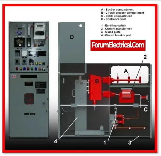
What is Metal-Clad Switchgear?
Electrical switchgear that is housed in a metal cabinet is known as metal-clad switchgear. A safe and dependable solution for use in medium-voltage applications, the metal cabinet offers a high level of safety for the electrical components.
In industrial & commercial conditions, where it is essential for the safety of the electrical system, metal-clad switchgear is frequently employed. The electrical grid can be isolated in some substations in the case of a malfunction due to the function of this type of equipment.
Metal-Clad Switchgear Testing and Commissioning
Electrical testing & commissioning of Metal-Clad switchgear is important to the safe start for the first time, regardless of the size, kind, or industry of the firm.
This post covers the testing and commissioning processes for all of the components of medium voltage switchgear, such as
- Circuit breakers,
- Busbars,
- Instrument transformers (current/voltage),
- Disconnect and grounding switches, etc.
Required Testing Equipment
- Micro ohmmeter
- Megger – Insulation Testing
- Torque wrench
- High voltage tester
Testing Procedure
Visual inspection and Mechanical checks
- Examine for physical problems or defects in all switchgear and components.
- Check the accuracy of the nameplate data.
- Check enclosing structures for appropriate alignment, foundation repair, grounding, and vermin entry.
- Examine the paintwork and good fit of all covers, panel sections, and doors.
- Verify the removal of all transport locks.
- Inspect the racking mechanisms, shutter, rollers, rails, and guides to make sure they are moving smoothly and correctly.
- Ensure the primary and secondary connections are properly aligned.
- Verify all mechanical interlocks are functioning properly.
- Verify that all connections with bolts are tight.
- Inspect the bus bar’s phasing connection to ensure it is right.
- Carry out the section-required mechanical examination & visual inspection for the breaker/contactor.
- Check instrument transformers’ mechanical condition and visually, in accordance with section
- Examine each disconnect/grounding switch mechanically and visually in accordance with the section.
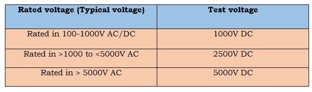
Insulation Resistance Test
It includes the
- Circuit breaker,
- Busbar,
- CT, and
- Panel enclosure.
Before starting the testing, the following measures should be carefully observed.
The component being tested will be visually inspected to make sure that any surface dust & moisture have been eliminated. Make sure the component is separated from any other connected systems so that it cannot send information back to other components (or) circuits that are not being tested.
Voltage must be applied during testing between one phase & the other phases that are linked to ground, and testing must be repeated for the other phases as described. Limits for test voltage are listed in the table below:
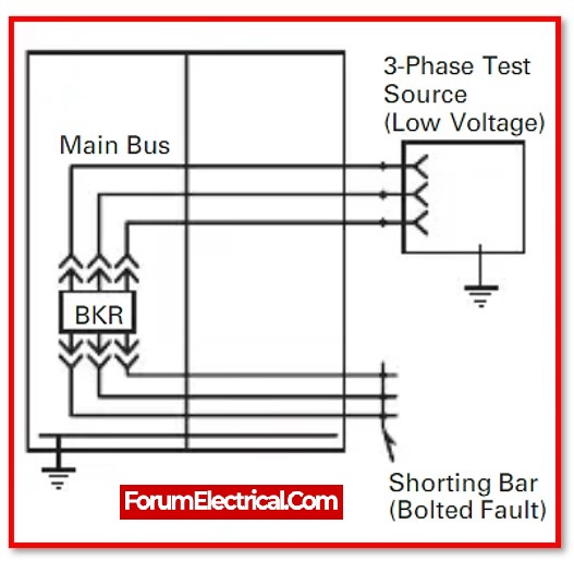
Contact Resistance Test
This test confirms that the bus-bar joints are correctly linked and tight.
The diagram following illustrates the test connection.
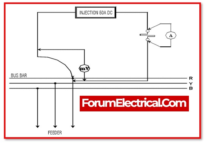
The test must be performed with CBs inserted & closed. Inject 100A DC to determine the contact DC resistance between panels. This includes
- Busbar joint,
- Circuit Breaker (CB) contact resistance,
- CB cluster resistance, and
- CT primary resistance.
High Voltage Test
In order to determine whether the equipment is in a healthy enough condition to continue in that state after installation to which it was constructed, and to provide some basis for forecasting whether the healthy condition will be maintained, or deterioration is occurring, which can result in an abnormally short life.
