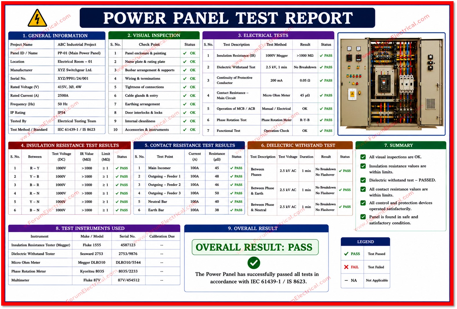
This report presents the findings of the routine and acceptance testing carried out on the Low Tension (LT) Main Power Distribution Panel identified above prior to its energization and commissioning.
Purpose
The purpose of this test is to verify that the panel and its associated
- Bus-bars,
- Protective devices,
- Interlocks and
- Metering equipment
have been manufactured, assembled and installed in accordance with the approved design drawings which is applicable Indian and international standards (IS 8623, IEC 61439) and the project specification.
All tests were carried out at site under controlled conditions with ambient temperature and humidity recorded to ensure the validity of insulation & continuity measurements.
Scope
The scope of testing covered visual and mechanical inspection, insulation resistance measurement, earth continuity verification, phase sequence checking, functional operation of circuit breakers and interlocks and protection relay pickup verification.
Each test was performed using calibrated instruments and results were compared against the acceptance criteria defined in the applicable standards and the panel manufacturers datasheet.
Test Objective
The primary objective of this test programme was to confirm the electrical integrity, mechanical function and operational readiness of the power panel before it is placed into service.
Specific objectives included:
Verifying that insulation resistance values between phases and between phases and earth, meet (or) exceed the minimum acceptable threshold.
Confirming correct mechanical operation of all moulded case circuit breakers (MCCBs) and associated interlocking mechanisms.
Validating earthing continuity & bonding of all exposed conductive parts.
Confirming correct phase sequence and absence of any wiring errors prior to energization.
Checking calibration & pickup accuracy of installed protection relays.
Document Identification
| Report No. | |
| Panel Designation | Main LT Power Distribution Panel (PDB-01) |
| Location | Electrical Room, Ground Floor, Main Building |
| Manufacturer | Rated 415V, 3-Phase, 4-Wire, 800A Panel |
| Rated Voltage / Current | 415 V AC, 800 A, 50 Hz |
| Test Date | |
| Tested By | Electrical Testing & Commissioning Team |
| Witnessed By | Client Representative / Consultant |
Test Instruments Used
The following calibrated instruments were used during the test.
All instruments carry valid calibration certificates traceable to a national standards laboratory and calibration validity was confirmed prior to commencement of testing.
| Instrument | Model / Sl. No. | Range | Calibration Due |
|---|---|---|---|
| Insulation Tester (Megger) | MIT 525 / 22145 | 0 – 2000 MΩ | Mar 2027 |
| Digital Multimeter | Fluke 117 / 88321 | 0 – 600 V | Jan 2027 |
| Primary Injection Test Kit | PCT – 320 / 30987 | 0 – 320 A | May 2027 |
| Earth Resistance Tester | ERT – 2000 / 15662 | 0 – 2000 Ω | Feb 2027 |
Test Conditions
Ambient Temperature: 31°C
Relative Humidity: 58%
Panel Status: De-energised, isolated & locked out (LOTO) prior to testing.
Test Voltage (Insulation Test): 1000 V DC, applied for 60 seconds.
Insulation Resistance Test Results
Insulation resistance was measured between each pair of phase conductors and between each phase conductor and earth, both before and after the application of test voltage to confirm there was no degradation in insulation integrity.
All recorded values are well above the minimum acceptable threshold of 100 MΩ specified for equipment of this voltage class.
| Test Point | Before (MΩ) | After (MΩ) | Min. Req. (MΩ) | Result |
|---|---|---|---|---|
| R–Y | 512 | 498 | 100 | PASS |
| Y–B | 487 | 475 | 100 | PASS |
| B–R | 530 | 521 | 100 | PASS |
| R–N | 460 | 452 | 100 | PASS |
| Y–N | 441 | 436 | 100 | PASS |
| B–N | 478 | 469 | 100 | PASS |
| Phase–Earth (avg.) | 395 | 388 | 100 | PASS |
Functional & Mechanical Test Results
Functional testing was carried out to confirm correct mechanical operation of
- Panels switching devices,
- Protective interlocks,
- Earthing arrangement and
- Indicating instruments.
Each instrument was inspected and exercised under supervision with results recorded against the defined acceptance criteria.
| Test Equipment | Acceptance Criteria | Observed | Result |
|---|---|---|---|
| Visual & mechanical inspection | No damage / defects | Satisfactory | PASS |
| Bus-bar torque check | As per manufacturer spec. | Within spec. | PASS |
| MCCB operation (open/close) | Smooth, no binding | Smooth operation | PASS |
| Interlock verification | Correct sequence | Verified correct | PASS |
| Earthing continuity | < 1 Ω | 0.42 Ω | PASS |
| Phase sequence | R-Y-B (clockwise) | R-Y-B confirmed | PASS |
| Indication lamps / meters | Functional | All functional | PASS |
| Protection relay pickup test | As per relay setting | Within tolerance | PASS |
| Door/panel earthing | Continuous bond | Continuous | PASS |
Observations
No physical damage, loose connections (or) signs of overheating were observed during the visual inspection.
Busbar joints were checked and torqued to the manufacturers recommended values using a calibrated torque wrench.
All MCCBs operated smoothly through their full travel with positive ON/OFF indication and mechanical and electrical interlocks between incomer and outgoing breakers functioned as designed that is preventing any incorrect switching sequence.
Earth continuity across all exposed metallic parts of the panel enclosure measured well within the acceptable limit of 1 ohm (1Ω).
Phase sequence at the incomer terminals was confirmed as R-Y-B in the clockwise direction that matching the upstream supply and the electrical panels design intent.
Recommendations
Re-torque all busbar & cable termination joints after 30 days of energized operation as a preventive measure.
Carry out periodic insulation resistance testing on an annual basis as part of routine preventive maintenance.
Maintain a log of relay trip settings & verify against the protection coordination study prior to final commissioning.
Ensure all danger/caution labels, single-line diagrams and panel schedules are affixed and legible on the panel door.
Schedule thermal imaging survey within the first month of full-load operation to detect any developing hot spots.
Conclusion
Based on the results of the
- Insulation resistance measurements,
- Functional and mechanical tests,
- Earthing verification and
- Protection relay
checks summarised in this report, the Primary LT Power Distribution Panel (PDB-01) is found to be in satisfactory condition and meets the acceptance criteria specified for insulation resistance, mechanical operation, interlocking and earthing integrity.
All recorded parameters are within the acceptable limits, and no non-conformances were identified during this round of testing.
The panel is therefore recommended for energization and commissioning, subject to the general recommendations noted in the following section and the closure of any punch-list items raised separately during the physical inspection.

