
What are Operator Control Devices?
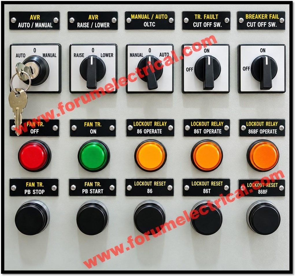
Push buttons and selector switches are human-machine interface devices mounted on control stations, machine doors and industrial panels.
They allow an operator to request actions such as starting, stopping, resetting (or) selecting an operating mode.
In most applications, the devices switch a control-circuit signal rather than directly carrying the motor power current.
The resulting signal may operate a contactor, relay, PLC input (or) another control-system component.
Push Buttons: Momentary Commands
A conventional momentary push button changes contact state while it is pressed and returns to its normal state when released.
A spring return mechanism is commonly used.
The contact block may contain a normally open (NO) contact, a normally closed (NC) contact (or) both depending on the model.
- START: commonly uses an NO contact. Pressing it closes the contact to request a start.
- STOP: commonly uses an NC contact. Pressing it opens the control path and requests a stop.
- RESET: Reset often uses an NO contact to send a reset request but the correct reset behavior depends on the control and safety design.
NO and NC Contacts
“Normally” describes the contact’s state when the actuator is in its defined normal, unoperated condition not whether the machine is running.
For a typical momentary push button:
| Contact type | Button not pressed | Button pressed |
| NO (Normally Open) | Open; no continuity | Closed; continuity |
| NC (Normally Closed) | Closed; continuity | Open; no continuity |
This distinction is fundamental during troubleshooting.
An NO START contact is expected to conduct only while pressed.
An NC STOP contact is expected to conduct in its normal state and interrupt the control path when pressed.
Verify the device contact diagram and test it de-energized and do not depend on cap colour alone.
Selector Switches: Maintained and Spring-Return Types
A selector switch lets the operator choose between defined positions.
A maintained selector stays in the selected position until moved again.
A spring-return selector returns automatically to a default position after the operator releases it.
Common configurations include
- Two-position switches (such as HAND/AUTO or ON/OFF),
- Three-position switches (such as LEFT/OFF/RIGHT) and
The labels and contact arrangement are application-specific.
For example, a HAND/AUTO selector may route a command through different control logic while a LEFT/OFF/RIGHT selector may select a direction command.
Electrical and mechanical interlocks must avoid incompatible commands from being active together where that could create a hazard.
A selector switch does not by itself guarantee safe isolation.
Terminal Numbers and Contact Identification
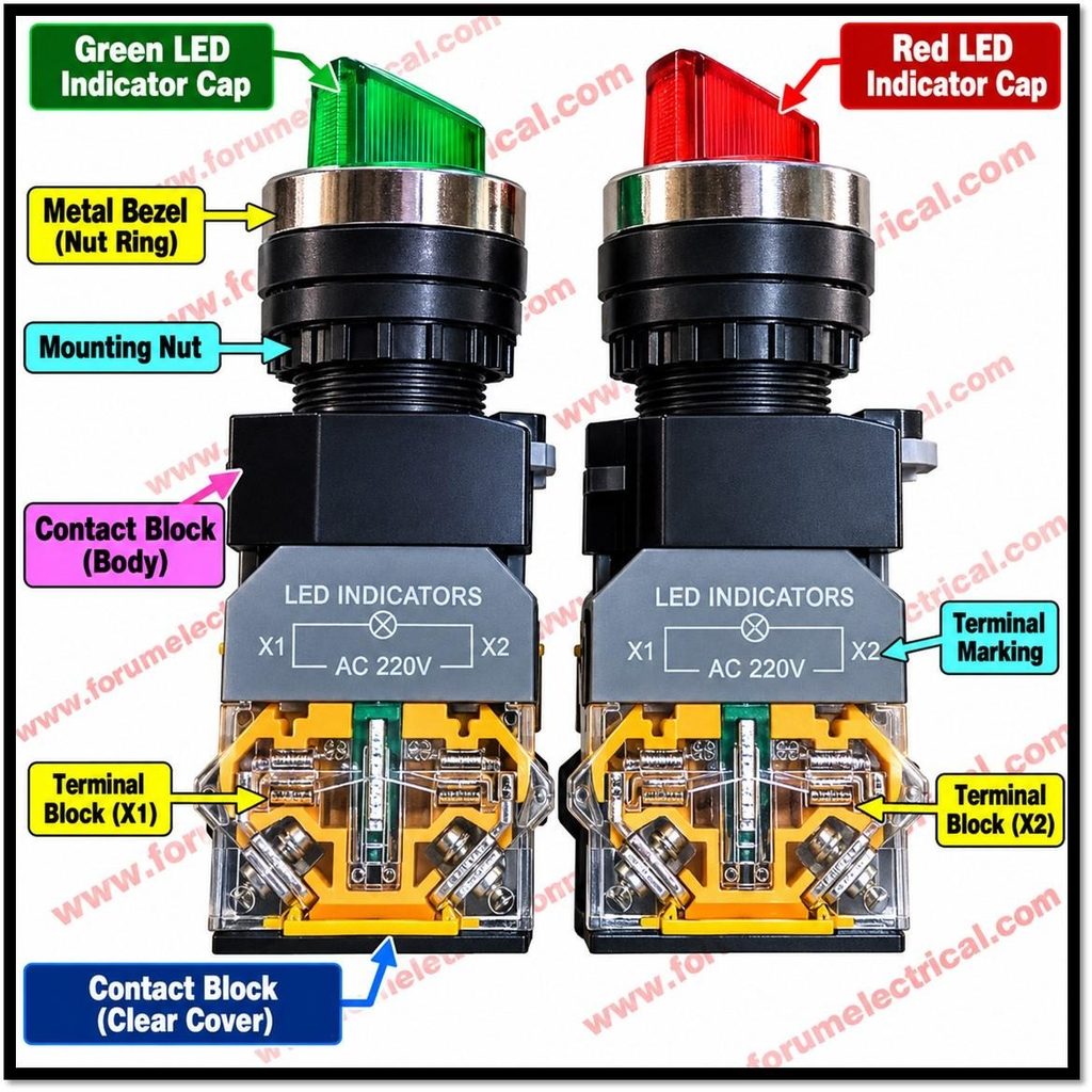
Terminal numbering varies with manufacturer, product family and contact-block type.
Some devices use 3–4 for an NO contact and 1–2 for an NC contact but this must not be treated as universal.
Under common IEC auxiliary-contact numbering conventions, 13–14 often identifies an NO contact and 21–22 an NC contact and these examples still need confirmation against the device markings and wiring diagram.
Identify the exact contact pair before wiring, continuity testing (or) replacement.
Typical START/STOP Motor-Control Circuit
A common 3-wire control circuit uses a STOP NC contact, an overload-relay NC trip contact, a START NO contact, a contactor coil and a contactor auxiliary NO contact for seal-in (holding).
The STOP and overload contacts are normally in series with the coil circuit.
The START NO contact is wired in parallel with the auxiliary holding contact.
- With the control supply available and the STOP and overload contacts healthy, the coil circuit is ready.
- Pressing START closes the START contact and energizes the contactor coil.
- The contactor main power contacts close to supply the motor while its auxiliary NO contact closes to maintain the coil circuit after START is released.
- Pressing STOP opens the NC stop path, de-energizing the coil; the main contacts open and the motor stops.
- If the overload relay trips, its control contact opens and drops out the contactor which subject to the circuit design.
Important:
A simple series path through STOP NC, START NO and the coil will normally run only while START is held.
The auxiliary holding contact is what provides the usual maintained-run behavior.
Real circuits may include additional permissives, interlocks, PLC logic and safety devices.
Inspection and Troubleshooting
If a machine does not respond correctly to START, STOP (or) a selector command, use the approved schematic and follow a systematic process:
- Confirm the reported symptom and check the control-power source, protective devices and control voltage specification.
- Verify the selector is in the intended position and check any mode-dependent permissives.
- Check the wiring, contact blocks, mechanical damage and indications of overheating once the equipment has been securely disconnected.
- Make sure the circuit is isolated and de-energized before using an appropriate meter to assess contact continuity.
- Check the STOP and overload control path, then the START contact and relevant interlocks in the sequence shown on the schematic.
- If qualified and permitted, perform energized voltage checks only under the site electrical-safety procedure and appropriate risk controls; compare readings with the circuit diagram and coil rating.
- Check contactor-coil resistance or operation only using the manufacturers method. Replace defective parts with compatible, correctly rated components and retest the complete function.
Safety Considerations
Isolate all relevant energy sources and apply the site Lockout/Tagout (LOTO) procedure before opening a panel, moving conductors (or) performing continuity checks.
Confirm absence of voltage with an appropriately rated tester and account for stored energy and alternate supplies.
Only competent, authorized personnel should carry out electrical work.
An emergency-stop function is a safety function, not a routine stop button.
Its design, reset behavior, monitoring and connection to safety relays or safety PLCs should follow the applicable machinery standards and risk assessment.
Do not bypass, bridge (or) defeat an emergency stop, guard interlock or other protective device to get a machine running.
Resetting an emergency stop should not automatically restart hazardous motion unless the validated safety design specifically permits it.
- NO contacts are open and NC contacts are closed in the defined normal, unoperated state.
- Terminal numbers and contact configurations should be verified from the actual device documentation.
- A typical START/STOP circuit uses a STOP NC path and a START NO contact with an auxiliary holding contact in parallel.
- Troubleshooting should be systematic, diagram-led and performed under appropriate isolation and electrical-safety controls.

