
Standard procedures for lighting and socket installation provide safety, efficiency, and adherence to electrical codes.
This post includes designing, wiring, mounting, testing, and safety inspections to guarantee that the electrical system operates properly and reliably.
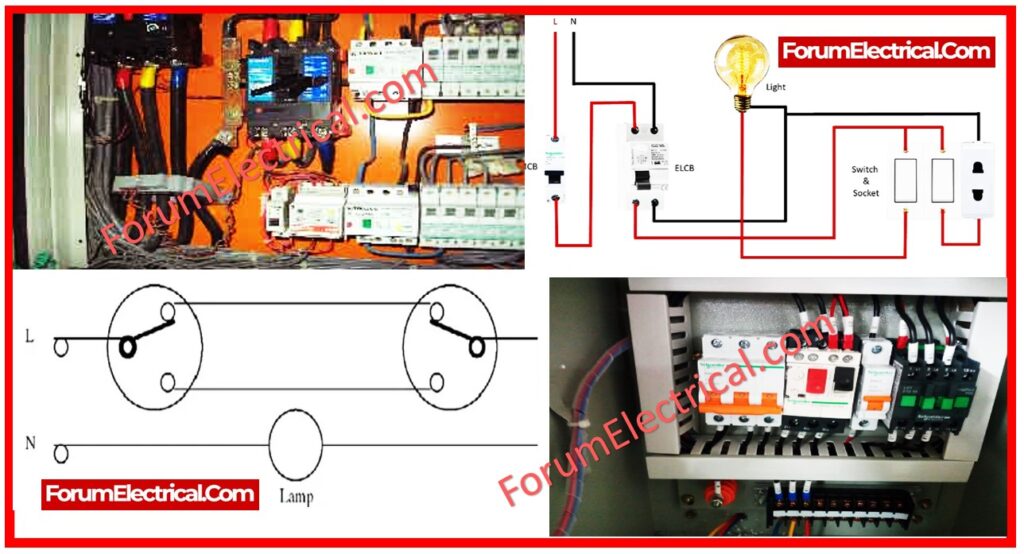
Scope
Supply, installation, and testing of the lighting system & combined power sockets.
Equipment Required
- Earth loop Impedance Tester
- Insulation Tester 500 VDC
- Lux Meter
- Hawk Saw
- Measuring Tape
- Drilling Machine
- Cutting Pliers
- Step Ladder for normal height
- Fish wire/Fish Tape
- Scaffolding for taller height
- Multimeter
Safety Equipment & PPE
- Helmet
- Goggles
- Dust Mask & Ammonia Gas Mask
- Safety footwear
- Stepladder/Scaffolding & Harness
- High Visibility Cloth (Yellow)
- Gloves
Responsibility
- Electrical Engineer
- Safety Officer
- Electrical Supervisor
Risk Identification
- Manual Handling
- Electrical fire (or) shock
- Slips and falls involving the use of a stepladder (or) scaffolding
- Use suitable tools and electrical equipment.
- Prior to the start of work, all risks associated with the project must be appropriately analyzed and managed.
Pre-Start Requirements for Location
- Follow client-specific site regulations and procedures.
- Prepare all necessary tools for the specified work.
- Ensured provision of safety & personal protective equipment.
- Ensure the operating environment is free of obstructions and hazards.
- Visually inspect tools needed for the proposed work.
Delivery, Storage & Handling
- Deliver lighting fixtures, sockets, and accessories safely and without damage or deformation. Package to prevent damage during shipping or handling.
- Carefully unload, store, and assemble lighting units, sockets, and accessories to avoid bending, warping, twisting, or surface damage.
- Keep lighting units, sockets, and accessories in a dry place with protective covering. Weather, odors, water, trash, and other potential hazards should be avoided.
Pre Installation Procedure
- Three-phase power sockets, single-phase power sockets of the industrial type, lighting fixtures, and g.s conduits will be allowed. The Engineer’s proposals will follow the approved site drawing in terms of size and routing.
Installation Procedure
- During the conduit system installation, the specified working and dressing practices must be used.
- All conduits for the lighting & power sockets (Exposed Installation) must be rigid galvanized conduits (Rigid heavy Gauge steel conduit) and meet specifications (Sub-Clause 3.3.2 section 260533), standards, and client recommendations.
- Conduit systems must be installed to guarantee compliance with the requirements of the Specified Standard and Regulation.
- The minimum and maximum conduit sizes to be used must be determined by the cable size, and conduit fill must be adequate to accommodate the lighting & power socket wires.
- Lighting power cable must be put in sturdy galvanized conduit after exiting the cable ladder and connected to the lighting fixture via appropriate size FRP termination boxes.
- The conduits must be securely fastened to the supporting channel using an approved conduit clamp. To avoid mechanical damage, the supporting clamp must be at least (2 m apart).
- Conduits and wireways not depicted on the Drawings must be selected in accordance with the Regulations, taking into account the quantity and size of conductors, as well as the space factor specified by the regulations. The minimum size of conduit for all applications is 20 mm diameter (I.D), unless otherwise specified on the drawings.
- The lighting fixtures shall be installed on steel structure on the mounting plates & brackets and on galvanized steel channels, and the location of the fixture shall be according to the approved shop drawings.
- Power sockets must be built at the appropriate height from floor level on channel supports, steel structures, or separate supports, depending on the situation on the job site.
- Before pulling cables, ensure that all conduits & cable ladder routes are complete & according to the design drawing, and that conduits are clear of blockages and burs. Additionally, all raceways must have 40% spare capacity.
- Cable for combined sockets should be put on cable ladder routes and then dropped out to the combined socket enclosure utilizing 50mm2 HDG conduits supported by adequate strut clamps or a 150mm cable ladder if necessary.
- Combined socket cable access to socket enclosure via stainless steel glands.
- When pulling the cables, take care not to exceed the manufacturer’s maximum draw tension.
- Pulled cables must be tested for continuity & insulation resistance prior to connection, with test results recorded and submitted.
- Ensure that all finishing work in all associated areas for the area of installation has been finished and that the civil section has released / cleared you to proceed with the installation of the lighting fixtures & power outlets.
- The type of lighting fixtures used must be in accordance with the approved lighting schedule and shop drawing.
- All lighting fixtures and electricity outlets must be connected with the earthing cable.
- All power socket enclosures and lighting fixture junction boxes must be tagged and sent for approval before installation.
- Luminaries are labeled with stainless steel labels that are secured to the neighboring surface using appropriate anchor screws.
- Fixtures and components that are not functioning properly should be replaced or repaired before retesting. Repeat the technique until the units work properly.
- Following installation, clean the fixtures both internally and externally. Use the methods and materials specified by the manufacturer.
- Adjust aimable fixtures to deliver the proper light intensities as necessary.
Test Procedure
Visual Inspection
Inspection of each piece of equipment’s condition, craftsmanship quality, alignment, perpendicularity, labeling, and so on, all in accordance with the specifications.
Illumination Measurements
Taken after 100 hours of “burn-in” at selected/approved places to determine level & consistency.
Operation and Functional
Inspect lighting installations for functionality, including control and regulatory equipment.
Emergency Lighting
Interrupt the electrical supply to ensure proper operation throughout the designated time period.
Documentation
All test results must be recorded & written.


