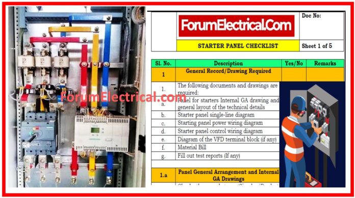
This organized post covers the essential electrical starter panel installation checks and documentation.
General Record/Drawing Requirements
Electrical panel installations require specific papers and drawings for planning, implementation, and verification.
Panel interior general arrangement (GA) drawing, single-line diagram (SLD), power and control wiring diagrams, variable frequency drive (VFD) terminal block diagram (if applicable), bill of materials (BOM), and test reports are important papers.
General Arrangement & internal GA Drawings
General Arrangement (GA) drawings show the panel’s arrangement for installation and maintenance.
The requirements should specify the panel type (Simplex/Duplex).
The plans must show the panel’s width, depth, and height and indicate a double door with the front access for outdoor panels.
GA designs should include
- Panel thickness,
- Indoor/outdoor protection,
- Paint shade,
- Texture finish,
- Sheet steel thickness,
- Cable entry/exit locations,
- Cable glands, and
- Mounting plates.
- Equipment mounting plates,
- Cable glands,
- Earthing connections,
- Bus bar diameters and
- Other components
should be included in the drawings.
All electrical components –
- MCBs,
- Relays,
- Contactors,
- Push buttons,
- Vfds,
- Switches,
- Meters, &
- Terminal blocks
must match the SLD and BOM.
The GA drawing title block should include project name, customer or consultant information, LOA number, & drawing number.
Power Wiring Diagram: Single or Three Line
The single-line diagram (SLD) is essential for panel electrical flow knowledge.
Check the SLD against the client (or) consultant’s specifications to confirm the feeder count is right.
Consider bus voltage, continuous current rating, and frequency, short-circuit (S.C) ratings, & bus bar material.
For each incoming and outgoing feeder, the SLD must list size, number of runs, material, voltage grade, & insulation.
Customer specifications should specify the starter system (DOL, VFD, Star Delta, or VFD/S-D bypass).
Please indicate if a control transformer feeder is needed for internal AC supply, wiring, & auxiliary devices like cooling fans, thermostats, door limit switches, tube lamps, plugs, and space heaters.
Analysis of Electrical Equipment Specifications
Electrical equipment connected to the panel should be tested for compatibility and ratings.
The SLD should indicate the load rated feeder and circuit breaker (ACB, MCCB, MCB, FSU, SFU, or fuse).
Identify the VFD type (GA70, J1000 series) and pole configuration (four-pole, three-pole, or three-pole & neutral).
Equipment ratings, legends, & accessories must match the SLD and BOM.
Metering needs should include meter type (electromechanical or digital) and communication capabilities.
The meter’s range and auto transfer requirements should be stated.
Details on current transformers (CTs) must include core count, ratio, accuracy class, burden, & knee point voltage.
Voltage Transformer (VT) feeders should have their winding count, vector group, primary protection, and other details examined.
Starter Panel Control Wiring Diagram
Starter panel control wiring diagrams are vital for electrical system operation and control.
Check the auxiliary supply to see if it comes from the incoming phase or a control transformer.
For VFD/ Star Delta bypass, DOL, Star Delta, and VFD starter systems, the wiring schematic should include auxiliary contactors and a selection switch for starting system mode & remote or local start.
Electrical & mechanical interlock mechanisms, space heater power circuit with thermostat, light bulbs, and outlets should be included in the control wiring design.
The wiring diagram should include all BOM components with legends. Terminal blocks for auxiliary supply, external interlock, fire damper, start/stop control, and BMS feedback should be incorporated.
Diagram of VFD Terminal Block
To meet client needs, the terminal block diagram should be reviewed if the panel has a Variable Frequency Drive (VFD).
The diagram should comprise a block diagram & PLC integration terminal blocks.
Legends should identify each VFD terminal block component.
Material Bill
An essential document, the Bill of Materials (BOM), lists all components, their ratings, make, material, & number.
Check that each component’s amount and specifications match the wiring diagram, SLD, & GA.
Check that all documentation matches component ratings and catalogue numbers.
Common Points
The tender standards must be met for feeder numbers and ratings in all paperwork and diagrams.
All aspects above should be checked against client or customer specifications, standards, and statutory bodies’ requirements to ensure electrical panel system compliance and functionality.


